
Related Manuals for RHEONIK RHE28


Summary of Contents for RHEONIK RHE28
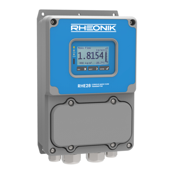
- Page 1 RHE28 Installation & Startup Guide RHE28 Installation & Startup Guide – Doc. No. 8.2.1.07 – Ver. 1.31 1 / 43 D o c u m e n t N o . : 8 . 2 . 1 . 0 7...
-
Page 2: Table Of Contents
Output Configuration ......................20 Analog Output Configuration ................... 20 Digital Output Configuration .................... 21 Digital Input Configuration ....................24 5 Remote Operation ......................25 RS485 ..........................25 RHE28 Installation & Startup Guide – Doc. No. 8.2.1.07 – Ver. 1.31 2 / 43... - Page 3 A.13 Contact address ........................ 35 Appendix B Technical Information .................. 36 Technical Data ........................36 Mechanical drawing ......................38 Appendix C CE Certificates ....................39 RHE28 Installation & Startup Guide – Doc. No. 8.2.1.07 – Ver. 1.31 3 / 43...
-
Page 4: General Information
General Information Important Safety Instructions for operating Coriolis Flowmeters For RHE28 units requiring 12 to 24V DC power, the use of a properly grounded (PELV) supply is highly recommended. The use of shielded cables for all I/O signals is recommended to prevent interference from high level EMI. -
Page 5: Quick Start
The RHE28 is a wall mount transmitter for installation in harsh environment. The standard enclosure rating is IP65 / NEMA 4, IP67 / NEMA 4X is available optionally. Technical data and dimensioned drawings of the RHE28 transmitter can be found in Appendix B. Electrical Installation Caution, the surface of the connection box may be hot if a hot fluid is running through the RHM sensor. -
Page 6: Interconnecting Rhe/Rhm
Other types of connector, such as those with screw terminals may be available and can also be used. RHE28 units are delivered with 2 x M16 cable glands and 2 x M25 blind covers as a standard. -
Page 7: Rhm Electrical Connection Type Tm (Ptfe Cable)
In situations where a high potential difference is present between the RHE and RHM, we recommend grounding via the PE C terminal on the RHM side. Figure 1: RHE28 Wiring with RHM Connection Types JM, SM & SC Upon power up, if the RHE indicates an error and the temperature measurement on the bottom right of the display shows “... -
Page 8: Rhm Electrical Connection Type Jo (12 Terminals)
RHM case and the RHE and the shield left both unconnected and isolated at the RHE or terminated to the PE connection via a 1nF capacitor. Figure 3: RHE28 Wiring with RHM Connection Types J6 & JO RHE28 Installation & Startup Guide – Doc. No. 8.2.1.07 – Ver. 1.31 8 / 43... -
Page 9: Legacy Rhm Sensors (9 Terminals)
RHM case and the RHE and the shield left both unconnected and isolated at the RHE or terminated to the PE connection via a 1nF capacitor. Figure 4: RHE28 Wiring with RHM legacy sensors RHE28 Installation & Startup Guide – Doc. No. 8.2.1.07 – Ver. 1.31 9 / 43... - Page 10 “ -.--°C/°F ” please check the temperature measurement configuration setting in the RHE (section 4.5). The correct temperature measurement configuration setting for an RHM legacy sensor is “1”. RHE28 Installation & Startup Guide – Doc. No. 8.2.1.07 – Ver. 1.31 10 / 43...
-
Page 11: Power Supply And Grounding
0.35mm² (AWG 22) for DC supply cables and 0.5mm² (AWG 20) for mains supply cables. The RHE28 do not contain a mains switch. A switch or circuit breaker close to the RHE28 must be included in the supply line. The switch must be marked correspondingly. -
Page 12: Ac And Dc Supply
Outputs DO3 and DO4 are control/status outputs only. Digital outputs are push-pull outputs compliant to IEC 60946. They can drive loads connected to ground and loads connected to +24V. RHE28 Installation & Startup Guide – Doc. No. 8.2.1.07 – Ver. 1.31 12 / 43... -
Page 13: Analog Outputs
3.2.3.2 Analog Outputs An RHE28 transmitter can be supplied with up to two 4-20 mA analog outputs. The outputs can be connected in a passive/floating configuration or as active outputs for ground referenced loads. Output 1 can optionally be equipped with a HART digital communications interface. -
Page 14: Digital Inputs
3.2.3.3 Digital Inputs RHE28 transmitters can be equipped with up to two IEC60946 compliant digital inputs. NOTE: Unless advised in advance of delivery, all digital inputs are configured by default for active high operation at the factory. Units with active low operational inputs are available upon request. -
Page 15: Analog Input
68 (PE) at the transmitter. The analog input in RHE28 transmitters certified for use with an RHM in a hazardous area includes certified barrier circuitry for connection with an intrinsically safe device. -
Page 16: Operation And Configuration
This chapter gives a short introduction into operation of the RHE28 through the front panel user interface. For more detailed information, please refer to the RHE2x Desktop Reference Manual. -
Page 17: Passcodes And Menu Selection
Figure 13: Example - RHE28 Top Level Menu Selection Passcodes and Menu Selection To configure and carry out certain functions in an RHE28 transmitter, it is necessary to enter a predetermined passcode. Passcodes protect configuration setup and prevent inadvertent changes to the flow meter operating condition. There are two different access levels with separate passcodes: “USER”... -
Page 18: Zero Offset Calibration
EXIT pushbutton twice. Change of Positive Flow Direction Rheonik mass flow meters are bi-directional and can operate with flow passing through them in any direction. In some cases after installation, the transmitter may read negatively because of orientation. -
Page 19: Temperature Measurement Configuration
RHM flow meter body requires accessing the temperature measurement configuration menu item as shown in Figure 16. Main Screen Figure 16: RHE28 Menu - Temperature Measurement Configuration RHE28 Installation & Startup Guide – Doc. No. 8.2.1.07 – Ver. 1.31 19 / 43... -
Page 20: Output Configuration
6. If necessary set a damping factor [C/B17] and damping band range [C/B18] If the RHE28 is equipped with only one analog output use “Analog Output 2 [B]” for configuration. -
Page 21: Digital Output Configuration
“Pulse Output” 1 [R] and/or 2 [S] must be disabled if the parameters “Digital Output” A [K] and/or B [L] are assigned to universal digital/pulse outputs of RHE28 2. Select a configuration for the pulse output according to the options stated in Table 9 under ID [R/S01] or for the status output under ID [I-L01] RHE28 Installation &... - Page 22 13: Mass Flow Rate RHE Compatibility Mode Frequency Output. → set [R/S04 & 07] Freq. mode of 14: Volume Flow Rate RHE Compatibility Mode Frequency Output. previous RHE → set [R/S05 & 07] RHE28 Installation & Startup Guide – Doc. No. 8.2.1.07 – Ver. 1.31 22 / 43...
- Page 23 Digital Output Channel 0 Alarm High: [I-L04] DigOutCh0/1/A/BAlmHigh Alarm high value, see DigOutCh0/1/A/BAlmType. Must be a floating point value of 0.0 or higher. See DigOutCh0/1/A/BAlmLow for the unit specification. RHE28 Installation & Startup Guide – Doc. No. 8.2.1.07 – Ver. 1.31 23 / 43...
-
Page 24: Digital Input Configuration
A transition from high to low at DI1/2 stops the totalizers when they are in the running state. A transition from low to high at DI1/2 restarts the totalizers when they are in the stopped state. RHE28 Installation & Startup Guide – Doc. No. 8.2.1.07 – Ver. 1.31 24 / 43... -
Page 25: Remote Operation
Manual for a detailed description of the interface and register set. The RHE28 transmitter features an internal 120 Ω termination resistor with a switch close to the RS485 terminals. Normally, the termination switch (and the factory default position) should be set to ON. -
Page 26: Service And Maintenance
RHE2X transmitters do not contain any user serviceable parts. Please contact your local sales/support agent or Rheonik Support for assistance. WEEE and RoHS RHE28 transmitters are not subject to the WEEE directive and are fully compliant to the RoHS directive. RHE28 Installation & Startup Guide – Doc. No. 8.2.1.07 – Ver. 1.31... -
Page 27: Ordering Code
Ordering Code RHE28 Installation & Startup Guide – Doc. No. 8.2.1.07 – Ver. 1.31 27 / 43... -
Page 28: Appendix A Ex-Safety Instructions
Always close unused cable glands and openings with dummy plugs. When installed in zone 2 or div. 2 the RHE28 must not be opened with any power connection alive. THE USB interface must not be used in hazardous areas. -
Page 29: System Description
– be mounted in zone 0, zone 1 or zone 2. For the American market versions for div. 1 and for div 2 are available. The RHE28 is an associated equipment and contains the barriers for the RHM to be connected. Depending on the certification the transmitter RHE28 may be mounted in the following areas:... -
Page 30: Thermal Safety Limits
Thermal Safety Limits The RHE28 with Ex-code A2, AB, C2 or CB have the temperature class T4 The RHE28 with Ex-code AS or Cs must be installed in the safe area, therefor no temperature class is specified for these units. -
Page 31: Installation
Special conditions for CSA certified units RHE28 marked Class I, Div. 2, Group A, B, C, D and/or Class I, Zone 2, A/Ex db [ia Ga] IIC T4 Gb 1. Shall be installed in class I, Division 2 / Zone 2 location. -
Page 32: Electrical Connection To Rhe
For the connection to the cage clamp terminals in the RHE28 the following rules apply: Conductor cross-section: 0.2 – 2.5mm² Stripping length: 6 – 9mm Electrical connection to RHE The figure shows the electrical connections between RHM*** -S* or –J* (connection box) and a RHE28. -
Page 33: Ordering Code
CSA (USA and Canada) C2 = class I, Div. 2 / Ex nA [ia Ga] IIC T4 Gc RHE28 in zone 2, Div. 2 CB = class I, Div. 2 / Ex nA [ia Ga] IIB T4 Gc As “C2”, but for gas group IIB... -
Page 34: Technical Data
3000m, higher maximum altitude upon request For the complete technical data refer to appendix B “Technical Data”. A.11 Compliance The RHE28 certified according to ATEX / IECEx comply with the following standards for hazardous areas: IEC 60079-0 IEC 60079-15 IEC 60079-11 For the list of standards relevant for a certain unit and for the release date refer to the certificate. -
Page 35: Service And Repair
The unit does not contain any user serviceable parts and must not be opened by the user. If the unit gets opened, the Ex-certification gets void. In case of malfunction connect your dealer or directly Rheonik Messtechnik GmbH A.13 Contact address Rheonik Messtechnik GmbH Rudolf-Diesel-Str. -
Page 36: Appendix B Technical Information
Appendix B Technical Information Technical Data General Data Housing: Wall Mount for harsh environment Material: Coated aluminum Enclosure Rating: IP65 / NEMA 4; IP67 / NEMA 4X optionally Ambient Temperature: -20°C to +60°C (-4°F to +140°F); -40 to +60°C optionally Humidity: 10 to 90% relative humidity, non-condensing Altitude:... - Page 37 Digital Status Outputs Output signal: Status Type: 24V push-pull, according to IEC60946 Maximum current: 20mA (high state), 100mA (low state) Quantity: 0 or 2, depending on I/O configuration Output value: programmable Digital Inputs Type: 24V, according to IEC60946 Input Level: >13V for high state, <...
-
Page 38: Mechanical Drawing
Mechanical drawing RHE28 Transmitter Dimensions (all dimensions in mm) Appendix B: Technical Information – Ver. 1.00 38 / 43... -
Page 39: Appendix Cce Certificates
Appendix C CE Certificates Appendix C: CE Certificates 39 / 43... - Page 40 Appendix C: CE Certificates 40 / 43...
- Page 41 Appendix C: CE Certificates 41 / 43...
- Page 42 Appendix C: CE Certificates 42 / 43...
- Page 43 D o c u m e n t N o . : 8 . 2 . 1 . 0 7 V e r s i o n 1 . 3 1 A P R - 2 0 2 1...
Need help?
Do you have a question about the RHE28 and is the answer not in the manual?
Questions and answers