Sign In
Upload
Manuals
Brands
RHEONIK Manuals
Transmitter
RHE42
User Manuals: RHEONIK RHE42 Mass Flow Transmitter
Manuals and User Guides for RHEONIK RHE42 Mass Flow Transmitter. We have
2
RHEONIK RHE42 Mass Flow Transmitter manuals available for free PDF download: Installation Manual, User Manual
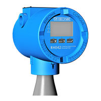
RHEONIK RHE42 User Manual (108 pages)
Coriolis transmitter
Brand:
RHEONIK
| Category:
Transmitter
| Size: 6 MB
Table of Contents
Table of Contents
5
About this Guide
7
General Information
7
Target Group
7
Storage
7
Declaration of Conformity
7
Symbols Used in this Guide
8
Safety
9
How Warnings Are Structured and What They Mean
10
Safety and Associated Safety Measures
11
Personnel Qualifications
12
Intended Use
13
Intended Use RHE42
13
Impermissible Use
13
Product Description
15
Model Code
18
Protection Classes and Safety Areas
20
Tion)
20
Transportation, Storage, Scope of Delivery
21
Installing the RHE42 Coriolis Transmitter
23
Installing the RHE42 Coriolis Transmitter Onto a Wall or Mounting Plate (RHE42-R*)
23
Installing the RHE42 Coriolis Transmitter on a Pipe
23
(Rhe42-R*)
23
Connecting the RHE42 Coriolis Transmitter
26
Connecting the RHE42 Coriolis Transmitter to the RHM Coriolis Sensor (RHE42-R*)
26
Connecting the Power Supply, Inputs/Outputs and Signal Cables to on the RHE42 Coriolis Transmitter
31
Modbus TCP
37
Connecting the Power Supply
37
Connecting the RS485 Interface
37
Connecting the Modbus TCP Interface
39
Connecting the Foundation Fieldbus / Profibus Interface
40
Wiring Diagrams for Non-Intrinsically Safe Inputs and Outputs
41
Connecting Non-Intrinsically Safe Analogue Outputs
41
Connecting Non-Intrinsically Safe Digital Outputs
42
Connecting Non-Intrinsically Safe Digital Inputs
43
Connecting a Non-Intrinsically Safe HART Interface
44
Wiring Diagrams for Intrinsically Safe Inputs and Outputs
45
Connecting Intrinsically Safe Analogue Outputs
45
Connecting Intrinsically Safe Digital Outputs
46
Connecting Intrinsically Safe Digital Inputs
46
Connecting an Intrinsically Safe HART Interface
47
Start-Up
49
Function of the Keys on the RHE42 Coriolis Transmitter
49
Operation
51
Initial Start-Up
53
Calibrating the Zero Point
54
Changing the Flow Direction
56
Reading out the IP Address
58
Setting up the RS485 Interface
59
Setting the Units of Measurement
61
Configuring Analogue Outputs
63
Configuring Digital Outputs
66
Configuring Digital Inputs
69
Performing an Output Test
72
Operation, Operating Modes, Using the Device
75
Resetting the Mass Flow and Volume Meters
75
Adjusting the Display Settings
76
Setting the Filter
78
10 Servicing, Maintenance
81
Assurance View
81
10.2 Reading out the Zero Point
82
11 Displaying Errors
85
12 Technical Data
91
13 Returns and Disposal
93
Appendix A: Ex-Safety Instructions
95
(Product Approval Information)
95
15 Appendices
105
Advertisement
RHEONIK RHE42 Installation Manual (109 pages)
Coriolis transmitter
Brand:
RHEONIK
| Category:
Transmitter
| Size: 7 MB
Table of Contents
Table of Contents
5
About this Guide
7
General Information
7
Target Group
7
Storage
7
Declaration of Conformity
7
Symbols Used in this Guide
8
Safety
9
How Warnings Are Structured and What They Mean
10
Safety and Associated Safety Measures
11
Personnel Qualifications
12
Intended Use
13
Impermissible Use
13
Product Description
15
Model Code
18
Protection Classes and Safety Areas (Explosion Protection)
20
Transportation, Storage, Scope of Delivery
21
Installing the RHE42 Coriolis Transmitter
23
Installing the RHE42 Coriolis Transmitter Onto a Wall or Mounting Plate (RHE42-R*)
23
Installing the RHE42 Coriolis Transmitter on a Pipe (RHE42-R*)
25
Connecting the RHE42 Coriolis Transmitter
26
Connecting the RHE42 Coriolis Transmitter to the RHM Coriolis Sensor (RHE42-R*)
26
Connecting the Power Supply, Inputs/Outputs and Signal Cables
31
To on the RHE42 Coriolis Transmitter
31
Wiring Diagrams for the Power Supply, RS485 and Modbus TCP
37
Connecting the Power Supply
37
Connecting the RS485 Interface
37
Connecting the Modbus TCP Interface
39
Connecting the Foundation Fieldbus / Profibus Interface
39
Wiring Diagrams for Non-Intrinsically Safe Inputs and Outputs
41
Connecting Non-Intrinsically Safe Analogue Outputs
41
Connecting Non-Intrinsically Safe Digital Outputs
42
Connecting Non-Intrinsically Safe Digital Inputs
43
Connecting a Non-Intrinsically Safe HART Interface
44
Wiring Diagrams for Intrinsically Safe Inputs and Outputs
45
Connecting Intrinsically Safe Analogue Outputs
45
Connecting Intrinsically Safe Digital Outputs
45
Connecting Intrinsically Safe Digital Inputs
46
Connecting an Intrinsically Safe HART Interface
47
Start-Up
49
Function of the Keys on the RHE42 Coriolis Transmitter
49
Operation
51
Initial Start-Up
53
Calibrating the Zero Point
53
Changing the Flow Direction
55
Reading out the IP Address
57
Setting up the RS485 Interface
58
Setting the Units of Measurement
60
Configuring Analogue Outputs
62
Configuring Digital Outputs
65
Configuring Digital Inputs
69
Performing an Output Test
71
Operation, Operating Modes, Using the Device
75
Resetting the Mass Flow and Volume Meters
75
Adjusting the Display Settings
76
Setting the Filter
78
10 Servicing, Maintenance
81
Reading out the Assurance Factor and Displaying the Assurance View
81
Reading out the Zero Point
82
11 Displaying Errors
85
12 Technical Data
91
13 Returns and Disposal
93
Appendix A: Ex-Safety Instructions (Product Approval Information)
95
15 Appendices
105
Advertisement
Related Products
Rheonik RHE16
Rheonik RHE45
RHEONIK RHE26
RHEONIK RHE27
RHEONIK RHE28
RHEONIK RHE21
RHEONIK RHE Series
RHEONIK RHE 49
RHEONIK RHE46
RHEONIK RHE 07
RHEONIK Categories
Transmitter
Measuring Instruments
More RHEONIK Manuals
Login
Sign In
OR
Sign in with Facebook
Sign in with Google
Upload manual
Upload from disk
Upload from URL