Vega VEGABAR 29 Operating Instructions Manual
Pressure sensor with metallic measuring cell, three-wire with io-link (2 x transistor or 4 20 ma plus 1 x transistor)
Hide thumbs
Also See for VEGABAR 29:
- Operating instructions manual (56 pages) ,
- Operating instructions manual (56 pages)

Subscribe to Our Youtube Channel
Related Manuals for Vega VEGABAR 29


Summary of Contents for Vega VEGABAR 29
- Page 1 Operating Instructions Pressure sensor with metallic measuring cell VEGABAR 29 Three-wire with IO-Link (2 x transistor or 4 … 20 mA plus 1 x transistor) Document ID: 57542...
-
Page 2: Table Of Contents
10.2 Rectify faults ........................28 10.3 Diagnosis, fault messages ..................... 29 10.4 Status messages according to NE 107 ................29 10.5 Software update ......................31 VEGABAR 29 • Three-wire with IO-Link (2 x transistor or 4 … 20 mA plus 1 x transistor) - Page 3 These instructions are attached as documents to each instrument with Ex approval and are part of the operating instructions. Editing status: 2020-08-31 VEGABAR 29 • Three-wire with IO-Link (2 x transistor or 4 … 20 mA plus 1 x transistor)
-
Page 4: About This Document
Numbers set in front indicate successive steps in a procedure. Battery disposal This symbol indicates special information about the disposal of bat- teries and accumulators. VEGABAR 29 • Three-wire with IO-Link (2 x transistor or 4 … 20 mA plus 1 x transistor) -
Page 5: For Your Safety
Canada This information is only valid for USA and Canada. Hence the follow- ing text is only available in the English language. VEGABAR 29 • Three-wire with IO-Link (2 x transistor or 4 … 20 mA plus 1 x transistor) - Page 6 Installations in the US shall comply with the relevant requirements of the National Electrical Code (ANSI/NFPA 70). Installations in Canada shall comply with the relevant requirements of the Canadian Electrical Code. VEGABAR 29 • Three-wire with IO-Link (2 x transistor or 4 … 20 mA plus 1 x transistor)
-
Page 7: Product Description
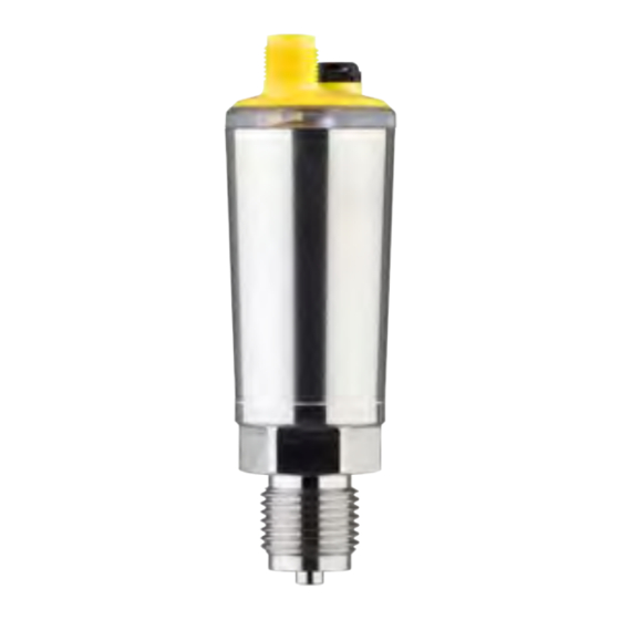
Software version from 1.2.0 Constituent parts Fig. 1: Components of VEGABAR 29 1 Process fitting Electronics housing LED illuminated ring Ventilation/pressure compensation Plug connector VEGABAR 29 • Three-wire with IO-Link (2 x transistor or 4 … 20 mA plus 1 x transistor) -
Page 8: Principle Of Operation
Principle of operation Measured variables The VEGABAR 29 is suitable for the measurement of the following process variables: • Process pressure • Level VEGABAR 29 • Three-wire with IO-Link (2 x transistor or 4 … 20 mA plus 1 x transistor) - Page 9 Measuring ranges up to 100 bar: piezoresistive sensor element with internal transmission liquid is used. Fig. 4: Configuration of the measuring system with piezoresistive sensor ele- ment Sensor element Base element Transmission liquid Process diaphragm VEGABAR 29 • Three-wire with IO-Link (2 x transistor or 4 … 20 mA plus 1 x transistor)
-
Page 10: Adjustment
• Smartphone/tablet (iOS or Android operating system) • PC/notebook (Windows operating system) Reduced effective range with M12 x 1 plug stainless steel (closed metal housing), see chapter "Technical Data" VEGABAR 29 • Three-wire with IO-Link (2 x transistor or 4 … 20 mA plus 1 x transistor) -
Page 11: Packaging, Transport And Storage
Avoiding mechanical shock and vibration • Storage and transport Storage and transport temperature see chapter " Supplement - temperature Technical data - Ambient conditions" VEGABAR 29 • Three-wire with IO-Link (2 x transistor or 4 … 20 mA plus 1 x transistor) -
Page 12: Accessories
Threaded adapters enable simple adaptation of devices with stand- ard threaded fittings, e.g. to process-side hygiene connections. Mounting accessories The suitable mounting accessories for VEGABAR 29 includes si- phons, blocking valves and measuring instrument holders. VEGABAR 29 • Three-wire with IO-Link (2 x transistor or 4 … 20 mA plus 1 x transistor) -
Page 13: Mounting
Tighten the cable gland or plug connector • Lead the connection cable downward in front of the cable entry or plug connector VEGABAR 29 • Three-wire with IO-Link (2 x transistor or 4 … 20 mA plus 1 x transistor) - Page 14 "Technical data" for the environment of the electronics hous- ing and connection cable are not exceeded. Fig. 8: Temperature ranges Process temperature Ambient temperature VEGABAR 29 • Three-wire with IO-Link (2 x transistor or 4 … 20 mA plus 1 x transistor)
-
Page 15: Process Pressure Measurement
Keep the following in mind when setting up the measuring system: • Connect via a siphon Fig. 10: Measurement setup for process pressure measurement of gases in pipelines VEGABAR 29 Blocking valve Siphon in U or circular form Pipeline VEGABAR 29 • Three-wire with IO-Link (2 x transistor or 4 … 20 mA plus 1 x transistor) -
Page 16: Level Measurement
Mount the instrument below the min. level • Do not mount the instrument close to the filling stream or emptying area • Mount the instrument so that it is protected against pressure shocks from the stirrer Fig. 12: Measurement setup for level measurement VEGABAR 29 • Three-wire with IO-Link (2 x transistor or 4 … 20 mA plus 1 x transistor) -
Page 17: Connecting To Power Supply
Connection procedure M12 x 1 plug This plug connection requires a complete confectioned cable with counter plug. VEGABAR 29 • Three-wire with IO-Link (2 x transistor or 4 … 20 mA plus 1 x transistor) -
Page 18: Wiring Plan
The output signal jumps to the set fault current • Switching outputs are controlled The current measured value is then output on the signal cable. With current output activated VEGABAR 29 • Three-wire with IO-Link (2 x transistor or 4 … 20 mA plus 1 x transistor) -
Page 19: Access Protection
The storage and transmission of the device codes is always encrypt- ed (SHA 256 algorithm). VEGABAR 29 • Three-wire with IO-Link (2 x transistor or 4 … 20 mA plus 1 x transistor) -
Page 20: Storing The Codes In Myvega
" PINs and Codes". This greatly simplifies the use of additional adjust- ment tools, as all Bluetooth access and device codes are automati- cally synchronized when connected to the " myVEGA" account VEGABAR 29 • Three-wire with IO-Link (2 x transistor or 4 … 20 mA plus 1 x transistor) -
Page 21: Setup With Smartphone/Tablet (Bluetooth)
This time gets longer after each incorrect entry. The message " Waiting for authentication" is displayed on the smart- phone/tablet. VEGABAR 29 • Three-wire with IO-Link (2 x transistor or 4 … 20 mA plus 1 x transistor) -
Page 22: Sensor Parameter Adjustment
The selected menu item, recognisable by the colour change, is dis- played in the right half. Fig. 16: Example of an app view - Setup measured values VEGABAR 29 • Three-wire with IO-Link (2 x transistor or 4 … 20 mA plus 1 x transistor) -
Page 23: Setup With Pc/Notebook (Bluetooth)
Enter Bluetooth access For authentication, enter in the next menu window the 6-digit code Bluetooth access code: VEGABAR 29 • Three-wire with IO-Link (2 x transistor or 4 … 20 mA plus 1 x transistor) -
Page 24: Parameter Adjustment
DTMs are compiled in a DTM Collec- tion. The DTMs can also be integrated into other frame applications according to FDT standard. VEGABAR 29 • Three-wire with IO-Link (2 x transistor or 4 … 20 mA plus 1 x transistor) - Page 25 8 Setup with PC/notebook (Bluetooth) Fig. 18: Example of a DTM view - Adjustment current output VEGABAR 29 • Three-wire with IO-Link (2 x transistor or 4 … 20 mA plus 1 x transistor)
-
Page 26: Menu Overview
Indication of the switching status 100 % Pressure unit mbar Unit temperature °C Bluetooth access code Device-specific access code Protection of the parameterization Deactivated Reset VEGABAR 29 • Three-wire with IO-Link (2 x transistor or 4 … 20 mA plus 1 x transistor) - Page 27 Basic setting VDMA 24574-1 Status Parameter modification counter Min. value pointer function Last values Max. value pointer function Sensor information INF, HW, SW Simulation VEGABAR 29 • Three-wire with IO-Link (2 x transistor or 4 … 20 mA plus 1 x transistor)
-
Page 28: Diagnostics And Servicing
VEGA service hotline under the phone no. +49 1805 858550. The hotline is also available outside normal working hours, seven days a week around the clock. VEGABAR 29 • Three-wire with IO-Link (2 x transistor or 4 … 20 mA plus 1 x transistor) -
Page 29: Diagnosis, Fault Messages
" Diagnostics" via the respective adjustment module. Adjustable via VEGA Tools app or PACTware/DTM VEGABAR 29 • Three-wire with IO-Link (2 x transistor or 4 … 20 mA plus 1 x transistor) - Page 30 Adjustment span too small F036 Failed or interrupted software update Repeat software update no operable sensor software F080 General software error Restart General software error VEGABAR 29 • Three-wire with IO-Link (2 x transistor or 4 … 20 mA plus 1 x transistor)
-
Page 31: Software Update
The device software is updated via Bluetooth. The following components are required: • Instrument • Voltage supply • PC/notebook with PACTware/DTM and Bluetooth USB adapter VEGABAR 29 • Three-wire with IO-Link (2 x transistor or 4 … 20 mA plus 1 x transistor) -
Page 32: How To Proceed If A Repair Is Necessary
Attach the completed form and, if need be, also a safety data sheet outside on the packaging • Ask the agency serving you to get the address for the return ship- ment. You can find the agency on our homepage. VEGABAR 29 • Three-wire with IO-Link (2 x transistor or 4 … 20 mA plus 1 x transistor) -
Page 33: Dismount
The device is made of recyclable materials. For this reason, it should be disposed of by a specialist recycling company. Observe the ap- plicable national regulations. VEGABAR 29 • Three-wire with IO-Link (2 x transistor or 4 … 20 mA plus 1 x transistor) -
Page 34: Certificates And Approvals
Germany. The published NAMUR recommendations are accepted as the standard in field instrumentation. The device fulfils the requirements of the following NAMUR recom- mendations: Exception: Versions with measuring ranges from 250 bar. These are subject of the EU Pressure Device Directive. VEGABAR 29 • Three-wire with IO-Link (2 x transistor or 4 … 20 mA plus 1 x transistor) -
Page 35: Environment Management System
" Packaging, transport and Lagestoragerung", " Disposal" of these operating instructions. VEGABAR 29 • Three-wire with IO-Link (2 x transistor or 4 … 20 mA plus 1 x transistor) -
Page 36: Supplement
5/10 Nm (3.688/7.376 lbf ft) Transmission liquid with measuring ranges up to 100 bar. With measuring ranges from 250 bar dry measuring cell. VEGABAR 29 • Three-wire with IO-Link (2 x transistor or 4 … 20 mA plus 1 x transistor) - Page 37 0 bar abs. 0 … 25 bar/0 … 2500 kPa +120 bar/+12 MPa 0 bar abs. Data on overload capability apply for reference temperature. VEGABAR 29 • Three-wire with IO-Link (2 x transistor or 4 … 20 mA plus 1 x transistor)
- Page 38 4 … 20 mA (active) Connection technology Three-wire Range of the output signal 3.8 … 20.5 mA (default setting) Signal resolution 5 µA VEGABAR 29 • Three-wire with IO-Link (2 x transistor or 4 … 20 mA plus 1 x transistor)
- Page 39 Output variable - Three-wire IO-Link Output signal IO-Link acc. to IEC 61131-9 Dynamic behaviour output Dynamic characteristics - Current output Depending on medium and temperature VEGABAR 29 • Three-wire with IO-Link (2 x transistor or 4 … 20 mA plus 1 x transistor)
- Page 40 TD 1 : 1 up to 5 : 1 peatability with 5 : 1 0.3 % < 0.3 % < 0.06 % x TD VEGABAR 29 • Three-wire with IO-Link (2 x transistor or 4 … 20 mA plus 1 x transistor)
- Page 41 Ʋ M12 x 1 plug, direct cable outlet IK05 acc. to IEC 62262 Process conditions Process temperature 0 … +100 °C (+32 … +212 °F) VEGABAR 29 • Three-wire with IO-Link (2 x transistor or 4 … 20 mA plus 1 x transistor)
- Page 42 (200 Pa SIP = Sterilization in place CIP = Cleaning in place MWP: Maximum Working Pressure Measuring ranges up to 100bar/10 MPa VEGABAR 29 • Three-wire with IO-Link (2 x transistor or 4 … 20 mA plus 1 x transistor)
- Page 43 Depending on the instrument version Depending on the local conditions; with plug M12 x 1 stainless steel (closed metal housing) effective range up to approx. 5 m (16.40 ft) = 35 V DC, output signal = 20 mA Load current = 250 mA VEGABAR 29 • Three-wire with IO-Link (2 x transistor or 4 … 20 mA plus 1 x transistor)
-
Page 44: Device Communication Io-Link
0x2B Frametypes, SIO-Mode, ISDU Revision ID 0x11 IO-Link Revision 1.1 Input process data length 4 Byte Output process data length 0 Byte VEGABAR 29 • Three-wire with IO-Link (2 x transistor or 4 … 20 mA plus 1 x transistor) - Page 45 Unsigned8 [2] RO 0x40, 0x00 cation PD-Descriptor 14 0x000E Unsigned8 0x01, 0x01, [12] 0x00, 0x01, 0x01, 0x01, 0x03, 0x0E, 0x02, 0x03, 0x0E, 0x10 VEGABAR 29 • Three-wire with IO-Link (2 x transistor or 4 … 20 mA plus 1 x transistor)
- Page 46 (FL1) Switching delay (DS1) 0x0108 Float 0.0 … 60.0 Reset delay (DR1) 0x0109 Float 0.0 … 60.0 Switching point (SP2) 0x010A Float VEGABAR 29 • Three-wire with IO-Link (2 x transistor or 4 … 20 mA plus 1 x transistor)
- Page 47 Unsigned8 0=individual 1=Acc to NAMUR NE 107 Failure 0x011F Unsigned8 0=Individu- ally colour, 1=Red, 2=Or- ange, 3=White, 4=Green, 5=Blue, 6=Yellow, 7=No signalling VEGABAR 29 • Three-wire with IO-Link (2 x transistor or 4 … 20 mA plus 1 x transistor)
- Page 48 Unsigned16 RW 1001=°C, 1002=°F Bluetooth access code 0x012D String Numerical value (BT) Protection of parameter 0x012E Unsigned8 0=deativated, adjustment 1=activated (with device code) VEGABAR 29 • Three-wire with IO-Link (2 x transistor or 4 … 20 mA plus 1 x transistor)
- Page 49 Simulation switching out- 0x0146 Unsigned8 0=Off, 1=On put 2 Simulation value 0x0147 Unsigned8 0=Open, 1=Close Device name 0x0148 String Serial number 0x0149 String VEGABAR 29 • Three-wire with IO-Link (2 x transistor or 4 … 20 mA plus 1 x transistor)
-
Page 50: Dimensions
Connection technology 26 mm (1.02") ø 36 mm ø 36 mm (1.42") (1.42") Fig. 24: Connection technology VEGABAR 29 Plug connector M12 x 1 Direct cable outlet VEGABAR 29 • Three-wire with IO-Link (2 x transistor or 4 … 20 mA plus 1 x transistor) - Page 51 ( 0.12 ") Fig. 25: VEGABAR 29, threaded fitting not front-flush DU Thread G½ (EN 837), manometer connection C2 Thread M20 x 1.5 (EN 837), manometer connection LF Thread ½ NPT, inside ¼ NPT (ASME B1.20.1) LY Thread ½ NPT (ASME B1.20.1) TI Thread ¼ NPT (ASME B1.20.1) TJ Thread G¼ (ISO 228-1) VEGABAR 29 • Three-wire with IO-Link (2 x transistor or 4 … 20 mA plus 1 x transistor)
- Page 52 LU Thread G½ (ISO 228-1) N9 Thread G¾ (DIN 3852-E) C5 Thread G1 (ISO 228-1) DA Thread G1½ (DIN 3852-A) C9 Thread 1½ NPT (ASME B1.20.1) VEGABAR 29 • Three-wire with IO-Link (2 x transistor or 4 … 20 mA plus 1 x transistor)
- Page 53 ø 40 mm ( 1.57 ") ( 1.57 ") Fig. 27: VEGABAR 29, cone/extension fitting DH Thread G1 (ISO 228-1), cone 40° LX Thread G1 (ISO 228-1), hygienic design VEGABAR 29 • Three-wire with IO-Link (2 x transistor or 4 … 20 mA plus 1 x transistor)
- Page 54 FR Varivent N50-40 PN 25 EZ Collar socket DN 40 PN 40 (DIN 11851) E2 Collar socket DN 40 PN 40 (DIN 11864-1, Form A) VEGABAR 29 • Three-wire with IO-Link (2 x transistor or 4 … 20 mA plus 1 x transistor)
-
Page 55: Industrial Property Rights
13.6 Trademark All the brands as well as trade and company names used are property of their lawful proprietor/ originator. VEGABAR 29 • Three-wire with IO-Link (2 x transistor or 4 … 20 mA plus 1 x transistor) - Page 56 Subject to change without prior notice © VEGA Grieshaber KG, Schiltach/Germany 2020 VEGA Grieshaber KG Phone +49 7836 50-0 Am Hohenstein 113...
Need help?
Do you have a question about the VEGABAR 29 and is the answer not in the manual?
Questions and answers