Advertisement
Quick Links
ALLEN + ROTH and logo design are
trademarks or registered trademarks of LF, LLC.
All rights reserved.
ATTACH YOUR RECEIPT HERE
Purchase Date _________________________
Questions, problems, missing parts? Before returning to your retailer, call our customer
service department at 866-439-9800, 8 a.m. - 8 p.m., EST, Monday - Sunday. You could also
contact us at partsplus@lowes.com.
AS22258
welcoming • sophisticated • inspiring
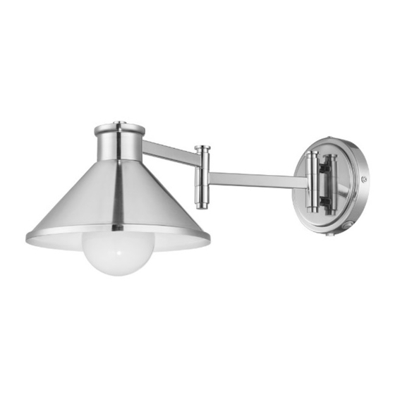
WALL SCONCE
1
RATED FOR
DAMP
LOCATIONS
ITEM #5024108
MODEL #42622
Español p. 13
Advertisement

Related Manuals for Allen + Roth 42622


Summary of Contents for Allen + Roth 42622
- Page 1 • sophisticated • inspiring RATED FOR DAMP LOCATIONS ITEM #5024108 ALLEN + ROTH and logo design are WALL SCONCE trademarks or registered trademarks of LF, LLC. All rights reserved. MODEL #42622 ATTACH YOUR RECEIPT HERE Español p. 13 Purchase Date _________________________ Questions, problems, missing parts? Before returning to your retailer, call our customer service department at 866-439-9800, 8 a.m.
-
Page 2: Table Of Contents
TABLE OF CONTENTS Package Contents..............3 Hardware Contents. -
Page 3: Package Contents
PACKAGE CONTENTS PART DESCRIPTION QUANTITY Fixture Metal Shade Socket Ring Switch (preassembled to Fixture [A]) Wall Plate (preassembled to Fixture [A]) Mounting Screws (preassembled to Wall Plate [E]) Power Cord (preassembled to Fixture [A]) Plug (preassembled to Power Cord [G]) Grommet (preassembled to Fixture [A]) (not drawn to scale) HARDWARE CONTENTS... -
Page 4: Safety Information
SAFETY INFORMATION Please read and understand this entire manual before attempting to assemble, operate or install the product. Failure to do so could lead to electrical shock, fire or other injuries that could be hazardous or even fatal. • Before you begin installing the light fixture, disconnect the power by removing fuses or turning off the circuit breakers. -
Page 5: Assembly Instructions For Plug-In Installation
ASSEMBLY INSTRUCTIONS FOR PLUG-IN INSTALLATION 1. Turn off the circuit breakers and the wall switch to the supply line leads. DANGER: Failure to disconnect the power supply prior to installation may result in serious injury or death. 2. This fixture has two options for installation. To install the fixture using the plug-in method, continue to the next step. - Page 6 ASSEMBLY INSTRUCTIONS FOR PLUG-IN INSTALLATION 4. Align the keyhole slots on the wall plate (E) with the screws (AH) on the wall and then gently push the wall plate (E) against the wall and slide down until secure. 5. Remove the socket ring (C) preassembled to the socket of fixture (A).
- Page 7 ASSEMBLY INSTRUCTIONS FOR PLUG-IN INSTALLATION 7. Insert plug preassembled to power cord (G) into nearby electrical outlet and move switch on underside of fixture (A) to ON position. Switch 8. The direction of the metal shade (B) can be changed using the adjustment hingeS.
-
Page 8: Assembly Instructions For Hardwire Installation
ASSEMBLY INSTRUCTIONS FOR HARDWIRE INSTALLATION 1. Turn off the circuit breakers and the wall switch to the supply line leads. DANGER: Failure to disconnect the power supply prior to installation may result in serious injury or death. 2. This fixture has two options for installation. To install the fixture using the hardwire method, continue to the next step. - Page 9 ASSEMBLY INSTRUCTIONS FOR HARDWIRE INSTALLATION 4. Remove the socket ring (C) preassembled to the socket of fixture (A). Lift the metal shade (B) and secure by reinstalling the socket ring (C) onto the socket. 5. Use the two mounting bracket screws (RR) to attach the mounting bracket (FF) to the outlet box (sold separately).
- Page 10 ASSEMBLY INSTRUCTIONS FOR HARDWIRE INSTALLATION 7. To remove the power cord (G) from the fixture (A), locate the two wires extending from the power cord (G). Lift the lever on the wire connectors preassembled to the fixture wires to release each plug wire.
- Page 11 ASSEMBLY INSTRUCTIONS FOR HARDWIRE INSTALLATION 10. Align the three holes in the edge of the fixture (A) with the three holes in the tabs on the mounting bracket (FF). Then use the three previously removed mounting screws (F) to secure fixture (A) to mounting bracket (FF).
-
Page 12: Troubleshooting
ASSEMBLY INSTRUCTIONS FOR HARDWIRE INSTALLATION 13. The direction of the metal shade (B) can be changed using the hinges. Note: Metal shade may get hot during operation. Ensure the shade is cool before adjusting the shade. Adjustment Hinge TROUBLESHOOTING PROBLEM POSSIBLE CAUSE CORRECTIVE ACTION Bulb will not light.
Need help?
Do you have a question about the 42622 and is the answer not in the manual?
Questions and answers