Table of Contents
Advertisement
Quick Links
OWNER'S GUIDE
Thru-Hull: 1kW
with Temperature Sensor
Tilted Element
Models: B164, B175H, B175HW, B175L, B175M,
SS164, SS175H, SS175HW, SS175L, SS175M
Pairs: B264N, B264W, SS264N, SS264W
U.S. Patent No. 7,369,45; 8,582,393. UK Patent No. 2 414 077
Follow the precautions below for optimal
product performance and to reduce the risk of
property damage, personal injury, and/or death.
WARNING: Always install the two set screws with
marine sealant applied to the threads. This will hold
the hull nut firmly in place. Failure to do so may allow
the hull nut to become loose.
WARNING: Always wear safety goggles and a dust
mask when installing.
WARNING: Immediately check for leaks when the
boat is placed in the water. Do not leave the boat
unchecked for more than three hours. Even a small
leak may allow considerable water to accumulate.
WARNING: Stainless steel housing in a metal hull—
Be sure the washer contacts the hull. Do not tighten
the hull nut with the washer against the isolation
bushing, as the housing will not be firmly installed. If
necessary, sand the isolation bushing until the washer
rests against the hull.
CAUTION: CHIRP transducer—Do not install in the
engine compartment or other hot place. The
transducer may fail if it overheats.
CAUTION: CHIRP transducer—Always operate the
transducer in water. Operating in air will allow the
transducer to overheat resulting in failure.
CAUTION: The arrow on the top of the transducer
must point toward the keel or centerline of the boat.
This will align the angle of the element inside the
transducer with the deadrise angle of your hull.
CAUTION: Never install a metal transducer on a
vessel with a positive ground system.
CAUTION: Never pull, carry, or hold the transducer by
its cable; this may sever internal connections.
CAUTION: Stainless steel housing in a metal hull—
Stainless steel housing must be isolated from a metal
hull to prevent electrolytic corrosion. Use the isolation
bushing supplied.
CAUTION: Never use solvents. Cleaner, fuel, sealant,
paint, and other products may contain solvents that can
damage plastic parts, especially the transducer's face.
IMPORTANT: For optimal performance, apply marine
sealant to the entire inside surface of the spacer. This
will fill the gap between the spacer and the sidewall of
the transducer preventing vibration.
IMPORTANT: Read the instructions completely
before proceeding with the installation. These
instructions supersede any other instructions in your
instrument manual if they differ.
&
Depth Transducer
™
Tilt Angles: 0
, 12
°
Installation INSTRUCTIONS
Record the information found on the cable tag for future reference.
Part No._________________Date___________Frequency________kHz
, 20
°
°
Applications
• Bronze housing recommended for fiberglass or wood hulls.
Never install a bronze housing in an aluminum hull, because
electrolytic corrosion will occur.
• Stainless steel housing compatible with all hull materials.
Recommended for metal hulls to prevent electrolytic corrosion
provided the stainless steel housing is isolated from the metal hull.
Match Tilt Angle of Transducer to Deadrise
Be sure your transducer model matches the deadrise angle of
your hull at the selected mounting location. The tilt angle is printed
on the top of the transducer (see Figure 1). To measure the
deadrise angle of your hull at the selected mounting location, use
an angle finder or a digital level (see Figure 2).
• 0° transducer for deadrise angles from 0° to 7°
• 12° transducer for deadrise angles from 8° to 15°
• 20° transducer for deadrise angles from 16° to 24°
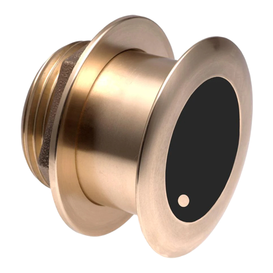
Figure 1. Top of transducer
Figure 2. Deadrise angle of the hull
B175H
130 - 210 kHz
(0° model shown)
Copyright © 2008 - 2012 Airmar Technology Corp.
transom view
Copyright © 2005 Airmar Technology Corp.
tilt angle
slope of hull
deadrise angle
parallel to waterline
Advertisement
Table of Contents

Related Manuals for Airmar Tilted Element B164


Summary of Contents for Airmar Tilted Element B164
- Page 1 Figure 1. Top of transducer (0° model shown) CAUTION: Never use solvents. Cleaner, fuel, sealant, Copyright © 2008 - 2012 Airmar Technology Corp. paint, and other products may contain solvents that can damage plastic parts, especially the transducer’s face. IMPORTANT: For optimal performance, apply marine sealant to the entire inside surface of the spacer.
- Page 2 I/O inboard 200kHz 50kHz stepped hull Figure 3. Best location for the transducer Figure 4. Connecting a Pair—single transmission line Copyright © 2007 - 2011 Airmar Technology Corp. Copyright © 2008 Airmar Technology Corp.
- Page 3 If the cable must be cut and Installing spliced, use Airmar’s splash-proof Junction Box No. 33-035 and 1. From outside the hull, thread the cable through the mounting follow the instructions supplied. Removing the waterproof hole.
- Page 4 (Europe, Middle East, Africa) Fax: +33.(0)2.23.52.06.49 accidentally cutting the outer skin. email: sales@airmar-emea.com 35 Meadowbrook Drive, Milford, New Hampshire 03055-4613, USA • www.airmar.com Copyright © 2007 - 2016 Airmar Technology Corporation. All rights reserved.
Need help?
Do you have a question about the Tilted Element B164 and is the answer not in the manual?
Questions and answers