Advertisement
Quick Links
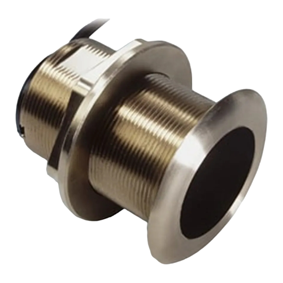
OWNER'S GUIDE
Thru-Hull:
Low-profile with Temperature Sensor
Tilted Element
Models:
B60, B117, P19, SS60, SS565
Chirp Models:
B75L/M/H/HW, B150M, SS75L/M/H
Patent http://www.airmar.com/patent.html
Follow the precautions below for optimal
product performance and to reduce the risk of
property damage, personal injury, and/or death.
WARNING: Always wear safety glasses, a dust mask,
and ear protection when installing.
WARNING: Immediately check for leaks when the
boat is placed in the water. Do not leave the boat
unchecked for more than three hours. Even a small
leak may allow considerable water to accumulate.
WARNING: B117, B150M—Do not use the spacer if
there is insufficient space to tighten the nut, or it is within
11mm (1/2") of the top of the housing.
WARNING: Stainless steel housing in a metal hull—
Be sure the washer contacts the hull. Do not tighten
the hull nut with the washer against the isolation
bushing, as the housing will not be firmly installed. If
necessary, sand the isolation bushing until the washer
rests against the hull.
CAUTION:
transducer—Always operate the
Chirp
transducer in water. Operating in air will allow the
transducer to overheat, resulting in failure.
CAUTION:
transducer—Do not install in the
Chirp
engine compartment or other hot place. The
transducer may fail if it overheats.
CAUTION: The arrow on the top of the transducer
must point toward the keel or centerline of the boat.
This will align the angle of the element inside the
transducer with the deadrise angle of your hull.
CAUTION: Never pull, carry, or hold the transducer by
its cable; this may sever internal connections.
CAUTION: Plastic housing—Never use a fairing with
a plastic housing; the protruding sensor would be
vulnerable to damage from impact.
CAUTION: Metal housing—Never install a metal
housing on a vessel with a positive ground system.
CAUTION: Stainless steel housing in a metal hull—
The stainless steel housing must be isolated from a
metal hull to prevent electrolytic corrosion. Use the
isolation bushing supplied.
CAUTION: Never use solvents. Cleaners, fuel, sealant,
paint and other products may contain solvents that can
damage plastic parts, especially the transducer's face.
IMPORTANT: Read the instructions completely before
proceeding with the installation. These instructions
supersede any other instructions in your instrument
manual if they differ.
&
Transducer
™
Tilt Angles: 0
, 12
, 20
INSTALLATION INSTRUCTIONS
Record the information found on the cable tag for future reference.
Part No:____________________Serial No:________________________
Date_______________Frequency____________________________kHz
Applications
• Plastic housing recommended for fiberglass or metal hulls only.
Never install a plastic housing in a wood hull since swelling of
the wood can fracture the plastic.
• Bronze housing recommended for fiberglass or wood hulls.
Never install a bronze housing in a metal hull, because
electrolytic corrosion will occur.
• Stainless steel housing compatible with all hull materials.
Recommended for metal hulls to prevent electrolytic corrosion
provided the stainless steel housing is isolated from the metal hull.
Match Tilt Angle of Transducer to Deadrise
Be sure the tilt angle of your transducer model matches the
deadrise angle of your hull at the mounting location. The tilt angle
is printed on the top of the transducer (Figure 1). To measure the
deadrise angle of your hull at the selected mounting location, use
an angle finder or a digital level (Figure 2).
• 0 models—For hull deadrise angles from 0 to 7
• 12° models—For hull deadrise angles from 8° to 15°
B75L, SS75L-12°—For hull deadrise angles from 0° to 24°
B75M, SS75M-12°—For hull deadrise angles from 6° to 15°
B75H, SS75H-12°—For hull deadrise angles from 6° to 15°
B75HW-12°—For hull deadrise angles from 6° to 15°
• 20° models—For hull deadrise angles from 16° to 24°
12° model
TILT
KEEL
12
AIRMAR®
Figure 1. Top of transducer
Copyright © 2005-2022 Airmar Technology Corp.
transom view
Figure 2. Deadrise angle of the hull
Copyright © 2005 Airmar Technology Corp.
P19
20° model
KEEL
O
AIRMAR®
[B117 shown]
slope of hull
deadrise angle
parallel to waterline
TILT
20
O
Advertisement

Related Manuals for Airmar Tilted Element B60


Summary of Contents for Airmar Tilted Element B60
- Page 1 Figure 1. Top of transducer [B117 shown] metal hull to prevent electrolytic corrosion. Use the Copyright © 2005-2022 Airmar Technology Corp. isolation bushing supplied. CAUTION: Never use solvents. Cleaners, fuel, sealant, paint and other products may contain solvents that can slope of hull damage plastic parts, especially the transducer’s face.
- Page 2 This will ensure there is marine sealant in the threads to Figure 3. Best location for transducer seal the hull and to hold the hull nut securely in place. Copyright © 2005 Airmar Technology Corp.
- Page 3 If the cable must be cut and element inside the transducer with the deadrise angle of your hull. spliced, use Airmar’s splash-proof Junction Box No. 33-035 and 2. From inside the hull, slide the washer onto the housing (Figure follow the instructions provided.
- Page 4 Apply only light pressure to the hole Tel: +33.(0)2.23.52.06.48 saw after cutting through the inner skin to avoid accidentally cutting the outer skin. email: sales@airmar-emea.com 35 Meadowbrook Drive, Milford, New Hampshire 03055-4613, USA • www.airmar.com Copyright © 2005 - 2022 Airmar Technology Corporation. All rights reserved.
Need help?
Do you have a question about the Tilted Element B60 and is the answer not in the manual?
Questions and answers