Table of Contents
Advertisement
Quick Links
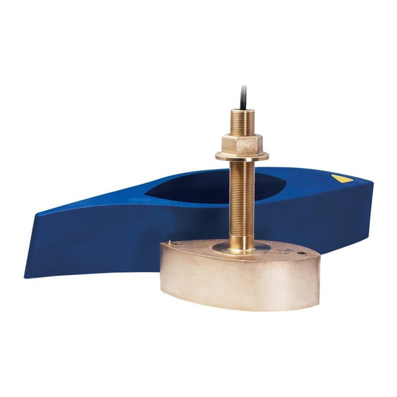
OWNER' S GUIDE & INSTALLATION INSTRUCTIONS
Thru - hull, Metal Stem,
Depth Transducer
Models: B45, B46, B240, B256,
B260, B261, SS505, SS560
IMPORTANT : Please read the instructions completely
before proceeding with the installation. These
instructions supersede any other instructions in your
instrument manual if they differ.
CAUTION : NEVER USE SOLVENTS
Cleaners, fuel, paint, sealants, and other products may
contain strong solvents, such as acetone, which attack
many plastics greatly reducing their strength.
Applications
• Bronze housing recommended for fiberglass or wood hulls.
Caution : Never mount a bronze housing in a metal hull,
because electrolytic corrosion will occur.
• Stainless steel housing compatible with all hull materials.
• Aluminum or steel hull —Use a stainless steel housing/stem
to prevent electrolytic corrosion.
Caution : Installation requires using a fairing kit to isolate the
stainless steel transducer from a metal hull.
• Caution : Never install a metal housing on a vessel with a
positive ground system .
Tools & Materials
Safety goggles
Dust mask
Electric drill
Drill bits:
Pilot hole
B45, B46, SS505
B240, B260, B261, SS560
B256
Sandpaper
Mild household detergent or weak solvent (alcohol)
File (installation in a metal hull)
Fairing ( mandatory for SS505 and SS560 )
Digital level or bubble level & protractor (installation w/ fairing)
Band saw or hand saw (installation with a fairing)
Rasp or power tool (installation with a fairing)
Marine sealant
Slip-joint pliers
Zip-ties
Water-based antifouling paint ( mandatory in salt water )
Installation in a cored fiberglass hull: (see page 4)
Drill bit for hull interior:
B45, B46, SS505
B240, B260, B261, SS560
B256
Cylinder, wax, tape, and casting epoxy
3mm or 1/8"
22mm or 7/8"
33mm or 1-5/16"
30mm or 1-3/16"
35mm or 1-3/8"
42mm or 1-5/8"
40mm, 41mm, or 1-5/8"
Record the information found on the cable tag for future reference.
Part No._________________Date___________Frequency________kHz
B45
High-Performance
Identify Your Model
The model name is printed on the cable tag.
About Fairings
Nearly all vessels have some deadrise angle at the mounting
location. If the transducer is mounted directly to the hull, the
sound beam will be tilted off the vertical at the same angle as the
deadrise. A fairing is strongly recommended if the deadrise angle
exceeds 10 ° .
• Orients the sound beam straight down by mounting the
transducer parallel to the water surface
• Minimizes aerated water flowing over the transducer's face by
mounting it deeper in the water
Airmar Polymer Fairing
Made of a high-impact polymer with an integrated cutting guide,
an Airmar fairing is safer and easier to cut with a band saw and
shape with hand tools than custom fairings. It can be shaped to
accommodate a deadrise angle of up to about 25 ° . (For fairing
part numbers, see "Replacement Parts" on page 4.)
A backing block is mounted inside the hull to provide a level
surface for the hull nut to seat against (see Figure 2). It is
fabricated matching the interior deadrise angle of the boat. After
cutting an Airmar fairing, use the remaining section with the
cutting guide for the backing block.
Airmar High-Performance Fairing
A high-performance fairing has a long streamlined shape for excel-
lent performance above 15 kn (18MPH) (see "Parts" on page 4).
Mounting Location
Acoustic Noise
Acoustic noise is always present and these sound waves can
interfere with the operation of the transducer. Background noise
from sources such as: waves, fish, and other vessels cannot be
controlled. However, carefully selecting the transducer mounting
location can minimize the effect of vessel generated noise from
the propeller(s) and shaft(s), other machinery, and other echo-
sounders. The lower the noise level, the higher the echosounder
gain setting that can be used.
standard
fairing
fairing
Advertisement
Table of Contents

Subscribe to Our Youtube Channel
Related Manuals for Airmar B240


Summary of Contents for Airmar B240
- Page 1 OWNER’ S GUIDE & INSTALLATION INSTRUCTIONS Thru - hull, Metal Stem, Depth Transducer Models: B45, B46, B240, B256, B260, B261, SS505, SS560 IMPORTANT : Please read the instructions completely before proceeding with the installation. These instructions supersede any other instructions in your instrument manual if they differ.
- Page 2 • The transducer will be continuously immersed in water. • There is a minimum deadrise angle. • The transducer beam is unobstructed by keel or propeller shaft(s). • There is adequate headroom inside the vessel for the height of the housing and tightening the nut.
- Page 3 7. Use the remaining section of the fairing for the backing block. Bedding Caution : Never pull, carry, or hold the transducer by the cable as this may sever internal connections. 1. Remove the hull nut (see Figure 2 or 5).
- Page 4 Checking for Leaks Warning : Never install a thru-hull transducer and leave the boat in the water unchecked for several days. When the boat is placed in the water, immediately check around the thru-hull transducer for leaks. Note that very small leaks may not be readily observed.
Need help?
Do you have a question about the B240 and is the answer not in the manual?
Questions and answers