Sign In
Upload
Download
Table of Contents
Contents
Add to my manuals
Delete from my manuals
Share
URL of this page:
HTML Link:
Bookmark this page
Add
Manual will be automatically added to "My Manuals"
Print this page
×
Bookmark added
×
Added to my manuals
Manuals
Brands
Chroma Manuals
Power Supply
62000L Series
User manual
Chroma 62000L Series User Manual
Programmable dc power supply
Hide thumbs
1
2
3
4
5
6
7
8
9
10
11
12
Table Of Contents
13
14
15
16
17
18
19
20
21
22
23
24
25
26
27
28
29
30
31
32
33
34
35
36
37
38
39
40
41
42
43
44
45
46
47
48
49
50
51
52
53
54
55
56
57
58
59
60
61
62
63
64
65
66
67
68
69
70
71
72
73
74
75
76
77
78
79
80
81
82
83
84
85
86
87
88
89
90
91
92
93
94
95
96
page
of
96
Go
/
96
Contents
Table of Contents
Bookmarks
Table of Contents
Table of Contents
General Information
Features & Operations
Precautions
Maintaining the 62000L Series
Product Users
Safety Information
Symbols and Terms
Electrical Specifications
Dimension
Preliminary Check
Power-On Check
Output Check
Voltage Output Check
Current Output Check
Input Power Check
Power-Line Cord Check
Power-Line Voltage Selection
Panel Check & Setting
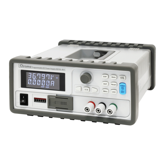
Front Panel Overview
Rear Panel Overview
Voltage & Current Limit Settings
Display Check
Power Supply Operation
Constant Voltage Operation
Constant Current Operation
Storing and Recalling Operation States
Setting the Overvoltage Protection
Setting the Overcurrent Protection
Overpower Protection
Remote Sensing
Constant Voltage Regulation
Output Rating
Output Interference
Stability
Remote Sensing Connections
Master & Slave Application
Connections in Series
Connections in Parallel
Other Settings for Multiple Connections
Turning off the Output
SEQ (Sequencing Mode)
System Operations
Error States
Beep/Alarm Settings
Display Control
OCP Delay (OCPDLY) Settings
Vrange
Style
Identification
SCPI Command Version
Calibration
Un-Secure Calibration
Securing Calibration
Changing the Security Code
Calibration Procedures
Calibration String
Remote Control Settings
Remote Interface Selection
USB Interface
GPIB Interface
Remote Control Reference
SCPI Language Summary
SCPI Language Introduction
Symbols Used in SCPI Commands
Command Format in this Manual
MIN and MAX Parameters
Setting and Querying Commands
SCPI Command Terminators
Common SCPI Commands
SCPI Parameter Types
SCPI Commands
Output Settings and Operation Commands
Triggering Commands
Trigger Source Options
Triggering Command Description
Output Control Commands
Commands for Master & Slave Application
Commands for Output Sequence
System-Related Commands
Calibration Commands
Status Reporting Commands
IEEE-488 Conformance Information
Programming Overview
Regarding Programming Ranges
Regarding SCPI Status Registers
The Questionable Status Register
The Standard Event Register
The Status Byte Register
Error Messages
Execution Errors
Self-Test Errors
Calibration Errors
Advertisement
Quick Links
1
Table of Contents
2
Remote Sensing
Download this manual
Table of
Contents
Previous
Page
Next
Page
1
2
3
4
5
Advertisement
Table of Contents
Need help?
Do you have a question about the 62000L Series and is the answer not in the manual?
Ask a question
Questions and answers
Related Manuals for Chroma 62000L Series
Power Supply Chroma 62000H Series Operating & Programming Manual
Programmable dc power supply (236 pages)
Power Supply Chroma 62000H Series Operating & Programming Manual
Programmable dc power supply (168 pages)
Power Supply Chroma 62020H-150S Operating & Programming Manual
Programmable dc power supply with solar array simulation (238 pages)
Power Supply Chroma 62100H-600S Operating & Programming Manual
Programmable dc power supply with solar array simulation (238 pages)
Power Supply Chroma 62050H-600S Operating & Programming Manual
Programmable dc power supply with solar array simulation (238 pages)
Power Supply Chroma 62150H-1000S Operating & Programming Manual
Programmable dc power supply with solar array simulation (238 pages)
Power Supply Chroma 62150H-600S Operating & Programming Manual
Programmable dc power supply with solar array simulation (238 pages)
Power Supply Chroma 62000P Series Operating & Programming Manual
Programmable dc power supply (138 pages)
Power Supply Chroma 62000P Series Operating & Programming Manual
Programmable dc power supply (171 pages)
Power Supply Chroma 62000D Series Operating And Programming Manual
Programmable bidirectiona dc power supply (180 pages)
Power Supply Chroma 62010L-36-7 User Manual
Programmable dc power supply (96 pages)
Power Supply Chroma 62015L-60-6 User Manual
Programmable dc power supply (96 pages)
Power Supply Chroma 62000B Series User Manual
Modular dc power supply (56 pages)
Power Supply Chroma 62015B-15-90 User Manual
Modular dc power supply (56 pages)
Power Supply Chroma 63610-80-20 Operation & Programming Manual
Programmable dc electronic load (258 pages)
Power Supply Chroma 63200 Series Operation & Programming Manual
High power dc electronic load (164 pages)
This manual is also suitable for:
62010l-36-7
62015l-60-6
Table of Contents
Print
Rename the bookmark
Delete bookmark?
Delete from my manuals?
Login
Sign In
OR
Sign in with Facebook
Sign in with Google
Upload manual
Upload from disk
Upload from URL


Need help?
Do you have a question about the 62000L Series and is the answer not in the manual?
Questions and answers