
Related Manuals for LNS TRYTON 107


Summary of Contents for LNS TRYTON 107
- Page 1 Instruction Manual TRYTON 107 / 112 LNS America 4621 East Tech Drive 9.112.03.US Cincinnati, Ohio 45245...
-
Page 3: Table Of Contents
CHAPTER 6: HYDRAULIC ..............55 HYDRAULIC EQUIPMENT ..................... 56 FILTER ............................ 58 CHAPTER 7: GENERAL DESCRIPTION ..........59 BARREL ..........................60 CONNECTOR .......................... 61 PUSHER ..........................62 MOVABLE VISE ........................63 LATERAL PIVOTING DEVICE / LOADING ARM (OPTION) ..........64 TRYTON 107/112... - Page 4 POWERING DOWN ....................... 89 CHAPTER 9: TROUBLESHOOTING/MAINTENANCE......90 FACTORS AFFECTING PERFORMANCE ................91 ALARMS ..........................94 MAINTENANCE ........................103 CHAPTER 10: APPENDICES ..............106 ORDERING FORM ....................... 107 PROGRAMMING EXAMPLE ....................108 LNS ADDRESSES & CONTACTS ..................109 TRYTON 107/112...
-
Page 5: Chapter 1: Basic Notions
CHAPTER 1: BASIC NOTIONS CHAPTER 1: BASIC NOTIONS TRYTON 107/112... -
Page 6: Structure
(see chapter *) or (see point *). 1.2. Captions Whenever possible, the reference numbers contained in the instruction manual are shown with the LNS ordering number of the indicated element. To make it easier to place an order of supplies, a form has been included in the annex at the end of this manual. -
Page 7: Rights
LNS SA. LNS SA and its subsidiaries cannot be held responsible for damage and problems arising from the use of options and products other than LNS products, or products approved by LNS SA. -
Page 8: Ec" Declaration Of Conformity
- Concerning the EMC Directive : EN 61000-6-4 : Generic emissions standard, Industrial environment • • EN 61000-6-2 : Generic immunity standard, Industrial environment Location and date : Stamp and signature : Orvin, November 28 , 2016 Mrs. Nadia Pellaton Manager Export Department TRYTON 107/112... -
Page 9: Safety Instructions
All persons who perform work on this machine, must have read and understood the notice instructions. LNS disclaim all responsibility for possible accidents or property damage caused when safety instructions are not followed : • Do not handle the equipment without having •... -
Page 10: Safety Devices
CHAPTER 1: BASIC NOTIONS 5. SAFETY DEVICES The TRYTON 107/112 bar feed system has been designed with a focus on maximum safety during its handling and complies with all EC requirements. Safety covers and devices make access to the moving parts of the bar feed system impossible. - Page 11 CHAPTER 1: BASIC NOTIONS 5.2. Layout of the safety elements SQ10 SQ11 Designation Description Main access cover Emergency Stop push button Safety switch for loading arm SQ10 (option, not represented in this picture) SQ11 Safety switch for main access cover TRYTON 107/112...
- Page 12 CHAPTER 1: BASIC NOTIONS TRYTON 107/112...
-
Page 13: Chapter 2: Technical Data
CHAPTER 2: TECHNICAL DATA CHAPTER 2: TECHNICAL DATA TRYTON 107/112... -
Page 14: Introduction
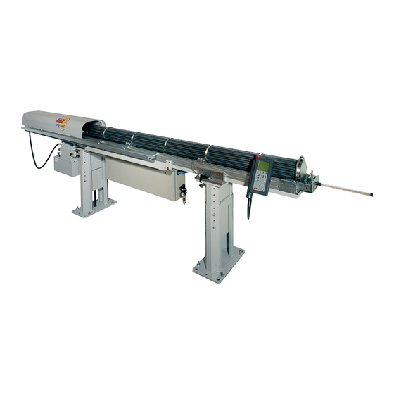
CHAPTER 2: TECHNICAL DATA 1. INTRODUCTION The TRYTON 107/112 bar loader is a worthy successor to the Tryton SST, which became a reference in its category and from which it has inherited the main qualities. While integrating the latest technological innovations, it offers users a range of surprising functions, while at the same time remaining simple to use and remarkably reliable. -
Page 15: Floor Plan
Details on the dimensions of other parts or elements of the bar feed system will be furnished upon request. The plan shows a feeder with right-hand loading (B). The measurements of feeders with left-hand loading (A) are the same. The views are merely reversed. TRYTON 107/112... - Page 16 CHAPTER 2: TECHNICAL DATA 3.1. Tryton 112 CNC TRYTON 107/112...
- Page 17 CHAPTER 2: TECHNICAL DATA 3.2. Tryton 107 cames/CNC TRYTON 107/112...
- Page 18 CHAPTER 2: TECHNICAL DATA 3.3. Tryton 112 cames TRYTON 107/112...
-
Page 19: Layout Of The Elements
Remote control Main access cover Front foot Rear foot Hydraulic tank Indexing motor Air filtering unit Pneumatic / electrical cabinet Connector feed motor Cable feed motor Material support Back stop Front stop Stationary control Loading arm (option, not represented) TRYTON 107/112... -
Page 21: Chapter 3: Setting Into Operation
CHAPTER 3: SETTING INTO OPERATION CHAPTER 3: SETTING INTO OPERATION TRYTON 107/112... -
Page 22: Transportation
Use an appropriate forklift truck to lift and transport the heavy components. 1.1. Description Depending on its destination, the TRYTON 107/112 bar feeder may be delivered either on a pallet or packed in a wooden crate. When transported by sea or air, the second solution is recommended. - Page 23 CHAPTER 3: SETTING INTO OPERATION The TRYTON 107/112 bar feeder is delivered as follows: The bar feeder is fully assembled and attached to the pallet with eight screws (A). • • A pusher is delivered installed in the bar feeder, and any additional accessories are delivered attached to the mount (B).
- Page 24 1.3. Preparation for mounting For mounting and installing the bar feeder, it is advisable to contact LNS or one of its agents. The latter cannot be held responsible for any malfunction resulting from an incorrect installation in which they did not take part.
- Page 25 INFO The distance between the lathe and the front of the bar feeder should not exceed 20 mm. If an obstacle requires a greater distance, contact LNS or its local representative. The area around the lathe and the bar feeder must be cleared to allow for their maintenance and handling.
-
Page 26: Mounting
The alignment may be carried out using a nylon string, an optical tool, etc. If you do not have any alignment tools, contact LNS or their local representative so they may take care of the bar feed system installation. On each foot, loosen the lock nuts (A) of the leveling screws (B). -
Page 27: Anchoring To The Ground
At this stage, the hydraulic tank may be filled. • For the electrical connection, please see Chapter 4, Electrics. For the pneumatic connection, please see Chapter 5, Pneumatics. • • For filling the tank, please refer to Chapter 6 / Hydraulics TRYTON 107/112... - Page 28 CHAPTER 3: SETTING INTO OPERATION TRYTON 107/112...
-
Page 29: Chapter 4: Electrics
CHAPTER 4: ELECTRICS CHAPTER 4: ELECTRICS TRYTON 107/112... -
Page 30: Electrical Equipment
Particular attention should be given to the handling of electrical elements because of risks of electrocution. In case of possible electrical malfunctions, it is advisable to contact LNS or their local representative. It is strictly prohibited to make adjustments as long as the bar feed system is under electrical power. - Page 31 Magnetic bar-end detector (not visible) 4.391 Detector: Positioning of control SQ4 SQ10 4.484 Loading arm security switch (option) SQ11 4.291 Main access cover safety switch 3.464 Pneumatic pressure switch 44.0179.K0.45 Hydraulic pressure switch 44.0094 Pulse generator: Counting (only for CNC) TRYTON 107/112...
-
Page 32: Stationary Control
CHAPTER 4: ELECTRICS 2. STATIONARY CONTROL The TRYTON 107/112 bar-feeder is equipped with a stationary control which is very useful when conducting mechanical adjustments to the feeder. This control is active only in manual mode. As soon as the feeder is in automatic mode, the stationary control becomes inactive. -
Page 33: Electrical Control Cabinet
Relay hydraulic pump M1 (advance pusher) KM1R 4.507 Relay hydraulic pump M1 (retract pusher) 4.815 Main circuit breaker 4A 4.503 Circuit breaker 2.5 to 4A 4.242 Main power switch R1-R5 4.925 Interface Relays 4.769 Transformer Single Phase 4.779 24 VDC Power supply 6.5A TRYTON 107/112... - Page 34 The power supply to the transformer is immediately interrupted to avoid material damages. After having located and repaired the problem causing this interruption, reset the lever (B) of the circuit breaker. Designation Description Power in connecting terminal Lever on/off Power out connecting terminal TRYTON 107/112...
- Page 35 Measure the power provided by the lathe, and, if necessary, adapt the cable on the power terminal block. Designation Description Primary terminal block, 220V-480V / 50hz or 60 Hz ± 15% Secondary terminal block, 230 V Fuse 3.15 A (230 VAC) TRYTON 107/112...
- Page 36 Run: The PLC is in RUN mode. This is the standard mode. Halt: The PLC is in HALT mode. Contact your LNS SA dealer. Error: The PLC is in a failure mode. Contact your LNS SA dealer. M1 slot: This slot is used by a flash (blue) card as memory expansion for the Parts Library. Do not remove the flash card unless instructed by LNS SA.
- Page 37 R3 + Relay : End of Bar + spindle Load command YV19 stopper (for cam lathe type) Workpiece load signal Relay : automatic mode Lathe door opened Relay : auxiliary End of Bar Reserve Reserve Reserve Reserve Reserve Reserve TRYTON 107/112...
-
Page 38: Interface
5.1. Description The interface cable(s), between the bar feed system and the lathe is (are) provided by LNS. Although an example of an interface diagram is provided, the diagram for the interface corresponding to your device, essential when making the electrical connection, is located inside the electrical cabinet. - Page 39 After the loading and positioning of the new bar on the lathe spindle, relay R2 confirms the end of the loading cycle or the part feed out. The operational cycle of relay R2 (pulsed, latched, etc.) is controlled by Services parameters. TRYTON 107/112...
- Page 40 Emergency Stop button are available for connection in the Emergency Stop circuit of the lathe. 5.2.4. Options The options described below are an integral part of the standard equipment of the LNS bar feed systems. These signals, however, are not required for the proper operation of the devices, or the safety locking for protecting persons and materials.
-
Page 41: Electrical Diagrams
CHAPTER 4: ELECTRICS 6. ELECTRICAL DIAGRAMS The electrical diagrams are contained in the electrical control cabinet. Should them differ from the one shown on the following pages, the one contained in the electrical cabinet should be referred to. TRYTON 107/112... - Page 42 CHAPTER 4: ELECTRICS Pont si pas de bras escamotable (SQ10) X2-EM4 X2-EM3 X2-EM2 X2-EM1 BARFEED STOP OF THE EMERGENCY TRYTON 107/112...
- Page 43 CHAPTER 4: ELECTRICS TRYTON 107/112...
- Page 44 CHAPTER 4: ELECTRICS TRYTON 107/112...
- Page 45 CHAPTER 4: ELECTRICS TRYTON 107/112...
- Page 46 CHAPTER 4: ELECTRICS Push Signal Start loading Auto cycle Collet signal TRYTON 107/112...
- Page 47 CHAPTER 4: ELECTRICS TRYTON 107/112...
- Page 48 CHAPTER 4: ELECTRICS TRYTON 107/112...
- Page 49 CHAPTER 4: ELECTRICS Batt Module TRYTON 107/112...
- Page 50 CHAPTER 4: ELECTRICS TRYTON 107/112...
-
Page 51: Chapter 5: Pneumatic
CHAPTER 5: PNEUMATIC CHAPTER 5: PNEUMATIC TRYTON 107/112... -
Page 52: Pneumatical Equipment
1.2. Layout of the pneumatic elements ZQ10 ZQ11 Designation Article nr. Description 3.636.US/3.638 Air filtering unit with air pressure switch 3.613 Valve assembly ZQ10 3.85012.N.10 Pneumatic cable-feed clutch cylinder ZQ11 3.85020.N.10 Pneumatic barrel-lock cylinder Pneumatic positioning stop cylinder ZQ12 3.85010.N.25 (only for CNC) TRYTON 107/112... -
Page 53: Air Filtering Unit
1. Unlock the adjusting knob by pulling it upward. To increase the pressure, turn it clockwise. To decrease it, turn it in the opposite direction. The operational pressure should be set at 5 bar. When the settings are done, lock the adjuster by pushing it downward. TRYTON 107/112... -
Page 54: Pneumatic Valve
The air pressure switch is directly integrated into the pressure gauge. Set up procedure for the pressure switch: • Remove the glass of the pressure gauge With a screwdriver, turn the setting screw • Place back the glass • TRYTON 107/112... -
Page 55: Pneumatic Diagram
CHAPTER 5: PNEUMATIC 4. PNEUMATIC DIAGRAM TRYTON 107/112... - Page 56 CHAPTER 5: PNEUMATIC TRYTON 107/112...
-
Page 57: Chapter 6: Hydraulic
CHAPTER 6: HYDRAULIC CHAPTER 6: HYDRAULIC TRYTON 107/112... -
Page 58: Hydraulic Equipment
1.1. Description The guidance principle of the TRYTON 107/112 bar-feeder consist in creating an oil film around the rotating bar that will help maintain it in the centre of the guidance tube thus avoiding all vibration and friction. - Page 59 Consult your supplier who will recommend the correct oil for you. To drain the hydraulic tank, place a container with sufficient capacity (minimum: 25 liters) underneath the tank, and unscrew the drain plug. Please refer to Chapter 9/Maintenance for cleaning the filter. TRYTON 107/112...
-
Page 60: Filter
CHAPTER 6: HYDRAULIC 2. FILTER TRYTON 107/112... -
Page 61: Chapter 7: General Description
CHAPTER 7: GENERAL DESCRIPTION CHAPTER 7: GENERAL DESCRIPTION TRYTON 107/112... -
Page 62: Barrel
Front stop 112.006.902 Indexing device 112.006.053 Rear stop 1.3. Hybrid barrel (option) The Hybrid barrels comprise two different diameters of guidance tubes. The procedure for passing from one working diameter to another is given in chapter 8 : OPERATION. TRYTON 107/112... -
Page 63: Connector
When extracting the remnant, the pusher is locked inside the connector block. 2.2. Layout of the elements Designation Description Connector Connector block Nozzle Locking screw Hydraulic fluid feed Proximity detector : positioning TRYTON 107/112... -
Page 64: Pusher
Article nr. Article nr. Article nr. Article nr. 112-15-114 112-15-124 112-15-134 112-15-144 Piston 1.440 1.441 1.442 1.443 Rear rotating sleeve 112-15-074 112-15-084 112-15-094 112-15-104 Body of pusher 1.440 1.441 1.442 1.443 Front rotating sleeve 15043/06-Ø 15033/07-Ø 15023/10-Ø 15013/12-Ø Collet TRYTON 107/112... -
Page 65: Movable Vise
When the bar is finished, the pusher retracts and the mobile vice extracts the remnant from the collet. 4.2. Layout of the elements Designation Description Upper arm Upper jaw adjusting screw Lower arm Lower jaw adjusting screw Lower jaw Upper jaw Roller-bearings Positioner Material presence verification plate Material presence verification probe TRYTON 107/112... -
Page 66: Lateral Pivoting Device / Loading Arm (Option)
When a lathe is equipped with a bar feed system, certain elements (motors, spindle reduction tubes, etc.) become inaccessible, and sometimes it is difficult, or even impossible, to proceed with their maintenance. To facilitate these tasks, the TRYTON 107/112 can be equipped with a loading arm, which allows the operator to move the bar feeder. -
Page 67: Cable Drive Assembly
CHAPTER 7: GENERAL DESCRIPTION 6. CABLE DRIVE ASSEMBLY TRYTON 107/112... -
Page 68: Chapter 8: Operation
CHAPTER 8: OPERATION CHAPTER 8: OPERATION TRYTON 107/112... -
Page 69: Powering Up
To power down, turn the switch to the left, to the 0off position. The main switch can be locked with a padlock. This way, it is impossible to turn the bar feed system on. Push (2) the locking mechanism and insert (3) the padlock into the opening. Lock the padlock TRYTON 107/112... -
Page 70: Remote Control
The remote control has five distinct segments, namely: display (A), function keys (B), directional keys (C), mode button STOP (D), and the emergency button (E). TRYTON 107/112... - Page 71 Pusher reverse (picture may be Automatic Top-Cut positioning in manual reversed) mode Confirm. In setup mode, the button must be hold for 3 seconds to Index the barrel validate the change. (until the icon disapear) Main setup menu Start the sequence TRYTON 107/112...
- Page 72 By pressing the STOP key, allows to exit the setting mode, regardless of the level reached, and to return to the work screen. The STOP key is not an emergency button, and cannot be interpreted as such. For emergency cases, always use the emergency button located on the top of the remote control. TRYTON 107/112...
-
Page 73: Set Up
3) Part length Before any operation, stop the lathe after machining a workpiece ! To modify any parameter, the bar feed system must bee in STOP mod. To check a parameter or validate a new parameter, maintain the key [ENTER]. TRYTON 107/112... -
Page 74: Mechanical Adjustments
4.1. Description The TRYTON 107/112 has several parameters and functions allowing the operator to configure it so that it adapts as closely as possible to the lathe on which it is installed, as well as to the production mode under way. - Page 75 Return the bar to the loading position. • Advance the mobile vice. Advance the connector and check that the bar is gripped and correctly inserted into the collet. • • Then, move the connector back to check that the rod is correctly extracted. TRYTON 107/112...
- Page 76 Once the pusher is in position behind the lathe collet slide the switch forward (1) until the indicator illuminates on the end of bar switch. • Fix in that position. Draw back the pusher then advance it again to ensure that it stops in the set position. • TRYTON 107/112...
- Page 77 5) Enter the new value with the numerical keys 6) To validate the new TOP CUT position, hold on [ENTER] key until the icon disappears (about. 2 sec.). 7) To exit adjustment mode, to press the [MENU] or [STOP] key. TRYTON 107/112...
- Page 78 6) Enter the new setting on the digital keypad 7) To save the new setting, hold on [ENTER] key until the icon disappears (about. 2 sec.). 8) To exit adjustment mode, to press the [MENU] or [STOP] key. TRYTON 107/112...
-
Page 79: Hybrid Barrel (Option)
10) Unscrew the bolt (C) and remove the connector block (D), taking care not to damage the cable (E). Place the connector block on the support provided for that effect. 11) Unscrew the cable (E) from the pusher (F). TRYTON 107/112... - Page 80 6) Fit the new ferrule (I). 7) Secure the ferrule with the cotter-pin (A). 8) More the connector to its rearmost position with the stationary control. 9) Index the barrel by one tube by pressing the LOAD button on the stationary control TRYTON 107/112...
-
Page 81: Loading
The front rest (option) must be correctly adjusted (opening and closing) and its elements must be • adapted to the shape of the material. On the lathe, the clamping device must correspond to the material to be loaded • TRYTON 107/112... - Page 82 The feed speed can be adjusted to between 50 and 200mm per sec. • Close the regulator slowly until the pressure falls. Reopen until the pressure stabilises. In this position the feed speed is at its minimum. To increase it, unscrew the regulator (C). TRYTON 107/112...
-
Page 83: Settings
• Settings relative to the parts conveyor Misc. functions Allows the access to specific settings like: • Language Factory settings • Dry Run mode • Service Reserved for maintenance to LNS technicians and for unlocking features / displays. TRYTON 107/112... - Page 84 The interface signal is reversed depending on whether the clamping 1 : NO device functions by pushing or by pulling. 2 : YES It is therefore essential to know the operation of the clamping device, without this, the feeding process cannot be done correctly. ENTER TRYTON 107/112...
- Page 85 When the headstock moves forward with open collet, this parameter ensure HEADSTOCK REVERSE that the bar stock position doesn’t change. WITH COLLET OPEN : For example if the collet stick to the bar stock. 1: NO 2: YES ENTER TRYTON 107/112...
- Page 86 In principle, this is set to 0 or 1. Ask your local LNS agent for PART SEPARATOR GOBLETS SYSTEM advice on this.
- Page 87 PRESS ENTER TO START without the bar feed system (chuck work, pre-heating of the lathe, etc.). In order to activate this parameter, the pusher and the movable vise must be in rear position and the main cover must be closed. TRYTON 107/112...
- Page 88 The service parameters allow to configure the bar feed system in its environment and to adapt the interface connected to the lathe. These parameters are protected with a password, because only LNS (or certified) technician is authorized to modify them. SERVICE PARAMETERS...
-
Page 89: Cycle Automatic
Only for CNC lathe type : on leaving the barrel, the bar pushes the positioning stop and the measuring path begins. Only for CAM lathe type: the timer set into parameters starts. Note : If the barrel is empty, the bar feeder stops when the jaws clamp to insert the bar into the pusher collet. TRYTON 107/112... - Page 90 Drawn by the retraction cable, the pusher moves back and recovers the remainder of the material. When the pusher is locked into the connector, the hydraulic motor stops turning and the connector retracts, taking the mobile vice with it. TRYTON 107/112...
-
Page 91: Powering Down
When powering off the barfeed, make sure the pusher is in reference position, table in lower position, and no bar stock is present in the guiding element. To power down, turn the switch to the left, to the 0 off position. TRYTON 107/112... -
Page 92: Chapter 9: Troubleshooting/Maintenance
CHAPTER 9: TROUBLESHOOTING / MAINTENANCE CHAPTER 9: TROUBLESHOOTING/MAINTENANCE TRYTON 107/112... -
Page 93: Factors Affecting Performance
In general, the difficulty increases with the specific weight of the bar. Steel bars are relatively easy to guide. Because of their great flexibility and specific weight, brass bars are relatively difficult to guide at high speeds. Aluminum bars of aluminum are very easy to guide. TRYTON 107/112... - Page 94 The radius of the grip is greater than the radius of the bar. The jaws press against only 3 points at 120 degrees. Correct: Modify the centers of the jaws to obtain 2 times 6 support clamping points at 60 degrees. TRYTON 107/112...
- Page 95 The inside diameter of the reduction tubes should be chosen in terms of the diameter of the bar (diameter of the bar + 1 mm), but should always be larger than that of the diameter of the feeding pusher. Spindle reduction tubes are available from LNS, upon request. 1.13. Shaped bars (hex and square) To load shaped bars, the feeder must be fitted with the appropriate gripping jaws.
-
Page 96: Alarms
Please read the safety precautions described at the beginning of this manual before handling the following devices. Particular attention should be given to the handling of electrical elements because of risks of electrocution. In case of possible electrical malfunctions, it is advisable to contact LNS or their local representative. 2.1. PLC alarms AL01 –... - Page 97 The problem is normally generated when the SQ2 switch mis-adjusted too close to the locking bracket. Solutions Adjust or replace switch SQ2. Adjust the barrel locking assembly. Press STOP key on the remote control to reset the alarm. TRYTON 107/112...
- Page 98 The problem is normally generated when the SQ5 switch is mis-adjusted and remains on after the transfer device has moved to the home position. Solutions Adjust or replace switch SQ5. Remove the obstruction keeping the transfer device from advancing all the way forward. Press STOP key on the remote control to reset the alarm. TRYTON 107/112...
- Page 99 Check and reconnect if necessary the pusher/piston to the retract cable. Check and adjust if necessary the disconnecting hook of the connector locking device. Remove any mechanical obstruction keeping the connector to move. Press STOP key on the remote control to reset the alarm. AL19 - Not used. TRYTON 107/112...
- Page 100 Le PLC has not received the signal of the clamping device in automatic production cycle. Solutions Check to see if the input changes while opening and closing the clamping device. Press STOP key on the remote control to reset the alarm. AL26 - Not used. TRYTON 107/112...
- Page 101 Check to see if the pusher got jammed in the channel. Make sure the guiding channels are seated correctly in the channel (maybe chips fell underneath the guiding channels). If the problem persists please contact LNS SA for further information. AL29 – PARTS SEPARATOR GOBLETS SYSTEM MALFUNCTION! Description This alarm occurs if any mechanical obstruction prevent the separator goblets to be correctly positionned or when the positioning motor is defective.
- Page 102 The alarm occurs mainly when the barrel is empty. Solutions Load bar stock into the barrel. AL36 - Not used. AL37 - Not used. AL38 - Not used. AL39 - Not used. AL40 - Not used. AL41 - Not used. AL42 - Not used. TRYTON 107/112...
- Page 103 Not used. AL47 - Not used. AL48 - Not used. AL49 - Not used. AL50 - Not used. AL51 - Not used. AL52 - Not used. AL53 - Not used. AL54 - Not used. AL55 - Not used. TRYTON 107/112...
- Page 104 AL56 – SINGLE BAR MODE ! Description This option allows to program the bar feed system and the lathe to stop after after machining one bar, set by the user. Solutions Restart the bar feed system and the lathe TRYTON 107/112...
-
Page 105: Maintenance
The battery must be replaced as soon as possible with a battery of the same type. Switching power off when the message “Battery low” could lead to loss of parameters. Don’t switch the power until the battery has been replaced. TRYTON 107/112... - Page 106 At no time should cleaning products come into contact with electrical components. 3.6. Spare parts Without the written consent of LNS SA, no addition or modification of the machine or spare parts can be undertaken. LNS SA assumes no responsibility when using spare parts which were not provided by LNS SA.
- Page 107 CHAPTER 9: TROUBLESHOOTING / MAINTENANCE TRYTON 107/112...
-
Page 108: Chapter 10: Appendices
CHAPTER 10: APPENDICES CHAPTER 10: APPENDICES TRYTON 107/112... -
Page 109: Ordering Form
CHAPTER 10: APPENDICES 1. ORDERING FORM This form should be photocopied, duly filled out, and returned to your retailer or nearest LNS agent Company name: Person in charge: Address: ZIP: City: Country: Phone: Fax: Type of device: Serial number: Qty. -
Page 110: Programming Example
N... N... N... X, Z, G, F, T, S, M, ... N... N... END OF PROGRAM (LOOP) Important: The above is an example only. Programming may change according to the interface between the lathe and the bar feed. TRYTON 107/112... -
Page 111: Lns Addresses & Contacts
CHAPTER 10: APPENDICES 3. LNS ADDRESSES & CONTACTS LNS Europe : www.lns-europe.com LNS America : www.lns-america.com LNS Asia : www.lns-asia.com TRYTON 107/112...
Need help?
Do you have a question about the TRYTON 107 and is the answer not in the manual?
Questions and answers