Takara Belmont YUME Installation Instructions Manual
Shampoo unit
Hide thumbs
Also See for YUME:
- Operating instructions manual (20 pages) ,
- Installation instructions manual (16 pages) ,
- Quick operation manual (12 pages)
Table of Contents
Advertisement
Quick Links
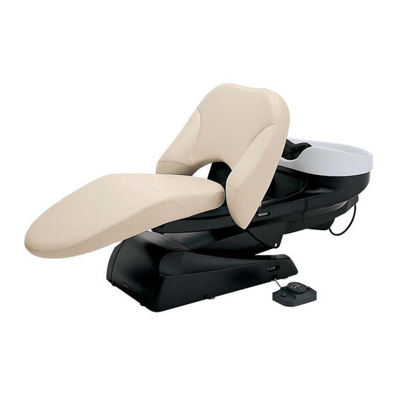
SHAMPOO UNIT
This manual provides information and instructions for YUME SHAMPOO
UNIT. The instructions contained in this booklet should be thoroughly read
and understood before attempting to install the equipment.
After the installation is completed, le this manual and refer back to it
for future maintenance.
YUME
IMPORTANT
INSTALLATION
INSTRUCTIONS
Version 6
2020.07
BEGB10D0
Advertisement
Table of Contents

Subscribe to Our Youtube Channel
Related Manuals for Takara Belmont YUME


Summary of Contents for Takara Belmont YUME
- Page 1 INSTALLATION INSTRUCTIONS IMPORTANT This manual provides information and instructions for YUME SHAMPOO UNIT. The instructions contained in this booklet should be thoroughly read and understood before attempting to install the equipment. After the installation is completed, le this manual and refer back to it for future maintenance.
-
Page 2: Table Of Contents
TABLE OF CONTENTS INST ALLA TION INSTRUCTIONS 1. Overall V iew and Major Components ... 1 2. Dimension & Specifications ......3. Plumbing Layout ........... 4. Contents of Unpacked Products ....4 5. Installation Instruction ........5-1. Preparations for Installations ...... -
Page 3: Overall View And Major Components
1. Overall View and Major Components ■Main Body Backrest Shampoo basin Original Installation date Month Year Service History Seat Hose replacement (1 ) Month Year Maintenance cover Main switch Foot switch Hose replacement (2 ) Month Year Hose replacement (3 ) Month Year Neck cushion... -
Page 4: Dimension & Specifications
2. Dimension & Speci cations Line for Edge of Base Plate Water Supply Hot Water Supply Drain Pipe Wall Wall Center of Drain Pipe 600 (Base Plate) 1270 Min.630(Sitting Position) Min.215 Min.430(Standing Position ) 1965 Min.2980(Sitting Position) / Min.2780(Standing Position) Type ------------------------------ EX-YMNL, EX-YMNR, SU-YM Drive System -------------------- Motorized Hydraulic System Measurement -------------------- 760 x 1985 x 975 mm (W x L x H) -
Page 5: Plumbing Layout
3. Plumbing Layout... -
Page 6: Contents Of Unpacked Products
Flexible Pipe ・ ・ Drain Hose Packing ・ Drain Hose Clamp ・ Valve Operation Manual ・ Installation instructions ・ YUME SPA Technical Manual(except for China) ・ ※Elbow and drain pipe(VU40) are NOT INCLUDED with shipment. Please prepare it beforehand. -
Page 7: Installation Instruction
5. Installation Instruction 5-1. Preparations for Installations 1. Unpacking Remove nails from lower part of wooden crate. Lift up the upper portion of wooden crate. Chair will be left on the skid. Nails Nails 2. Remove the pump cover . 1. -
Page 8: Marking For Unit Fixing Position
5-3. Marking for unit xing position Use supplied full scale template to mark the Marking xing position on the oor r . Check the piping and power outlet position before marking. Water Supply Pipe 1. Put the supplied templete on the oor and hold with the tape etc. - Page 9 2. Hold the carriage jig and move the main unit to marked position on the oor . 3. Decide the installation position and remove the carriage jig A and B from main unit base. CAUTION Carriage Jig B Hold the Jig A and B to lift the unit by Carriage Jig A 2 workers to move it.
-
Page 10: Drain Pipe Connection
5-6. Drain Pipe Connection Drain pipe(VU40) Elbow and drain pipe(VU40) are not included Drain Hose Packing with shipment. Please prepare it beforehand. Stepped Section Insert the drain hose packing 1. Insert the elbow to the drain pipe from floor with seals. to the drain pipe(VU40) until the stepped section hit to the end of drain pipe(VU40). -
Page 11: Unit Power Supply Line
5-8. Unit Power Supply Line Power Supply Cable 1. Fix the plug on the end of the unit power supply cable. Power Supply Outlet Plug the unit power supply plug into the suitable power supply outlet. 5-9. Installation of Base Cover 1. -
Page 12: Attach The Backrest And Seat Cushion
5-10. Attach the backrest and seat cushion 1. Fix the seat cushion with six cap bolts(M5×15) 2. Fix the seat cover L & R with screws. 4. Backrest Cushion Attach the backrest cushion 3. Keep depressing backrest raising button vertical to the backrest frame. until the backrest frame is raised position. -
Page 13: Attach The Neck Cushion
5-11. Attach the Neck Cushion Neck Cushion Hook 1. Attach the neck cushion on metal ttings as shown in gure. Fixed Pin Metal Fitting 2. Both side hooks of the neck cushion is xed on a xed pin. Hook Hook 5-12. - Page 14 NOTE TAKARA BELMONT CORPORA TION 1-1, 2-Chome, Higashi-shinsaibashi,Chuo-ku,Osaka,Japan TEL : (06) 6213-5945 AX : (06) 6212-3680 Printed in Japan...
Need help?
Do you have a question about the YUME and is the answer not in the manual?
Questions and answers