
Related Manuals for FlowLine Switch-Pro AU18 Series


Summary of Contents for FlowLine Switch-Pro AU18 Series
- Page 1 Switch-Pro™ w/ Compact Junction Box AU18 & AZ18 Series Owner’s Manual Flowline, Inc. |. 10500 Humbolt Street, Los Alamitos, CA 90720. p 562.598.3015. f 562.431.8507. w flowline.com MN301460 Rev A...
-
Page 2: Table Of Contents
Introduction / Table of Contents Step One Intended for side wall installation, the general-purpose level switch package provides reliable liquid level detection with single 60 VA relay and a compact junction box for integral wiring termination. Offered in two level sensor technologies, select the type and material based upon your application media. -
Page 3: Specifications
Specifications / Dimensions Step Two Accuracy: ± 1mm in water Repeatability: ± 0.5mm in water Supply voltage: AZ18: 12-30 VDC AU18: 12-36 VDC Consumption: 25mA maximum Contact type: (1) SPST Relay Contact rating: 60VA, 1A max. Contact output: Selectable NO or NC Process temp.: F: -40°to 176°... -
Page 4: Components
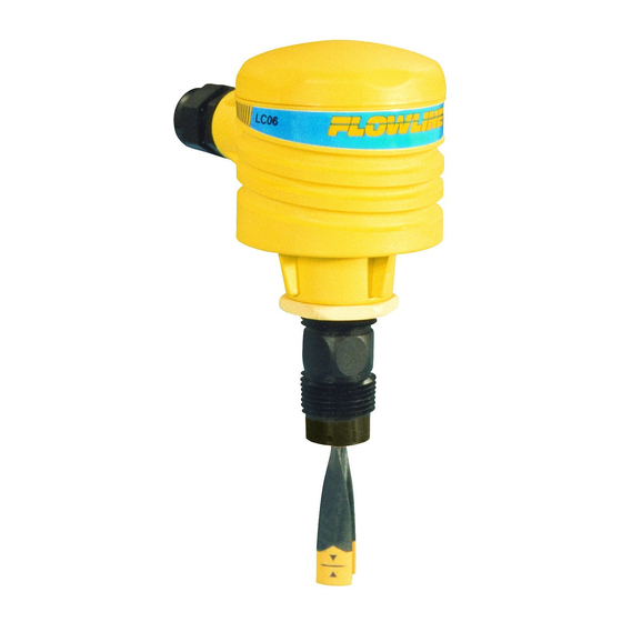
Step Three ABOUT SWITCH-PRO™ Flowline’s Switch-Pro™ with Compact Junction Box is a single-point mounting system for installing through the sidewall of a tank. The compact junction box features termination for the various wires (6-pin terminal block) from the level switch as well as a 1/2” conduit connection. - Page 5 Technology Step Four VIBRATION SWITCH (AZ18-113 _ SERIES) The vibration switch (tuning fork) operates at a nominal frequency of 400 Hz. As the switch becomes immersed in a liquid or slurry, a corresponding frequency shift occurs. When the measured frequency shift reaches the set point value, the switch changes state indicating the presence of a liquid or slurry medium.
- Page 6 Technology (continued) Step Four ULTRASONIC SWITCH (AU18-113 _ & AU18-213 _ SERIES) The Ultrasonic level switch generates a 1.5 MHz ultrasonic wave from a miniature piezoelectric transducer located on one side of the gap within its sensing tip. Another piezo transducer, located on the other side of the gap, acts as a microphone, picking up the sound wave.
-
Page 7: Safety Precautions
Make a Fail-Safe System: Design a fail-safe system that accommodates the possibility of system or power failure. In critical applications, Flowline recommends the use of redundant backup systems and alarms in addition to the primary system. While this manual offers some examples and suggestions to help explain the operation of FLOWLINE products, such examples are for information only and are not intended as a complete guide to installing any specific system. - Page 8 Assembly of Switch-Pro™ Step Four About Switch-Pro™: Flowline’s Switch-Pro™ with Compact Junction Box Assembly is a single-point mounting system for installing one level sensor horizontally within a tank. The compact junction box features termination for the various wires from each level switch as well as a 1/2” conduit connection. Switch- Pro™...
- Page 9 Wiring Step Eight ULTRASONIC AND VIBRATION SWITCHES The LU10-14_5 and LZ12-14_5 switch can be wired normally open or normally closed for your application requirement. Each ultrasonic switch requires 12 - 36 VDC power while each vibration switch requires 12-30 VDC power to operate the sensor and switch the relay. The relay output can be wired as a dry contact. All illustrations below identify a Dry switch state as the normal position of the relay.
-
Page 10: Installation
THROUGH WALL INSTALLATION Flowline’s Switch-Pro™ A_18 series may be installed through the side wall of a tank. The sensor has male 3/4" NPT (3/4” G) threads on one side of a 15/16" wrench flat. This enables the user to select the sensor’s mounting orientation, installed outside of the tank in. -
Page 11: Maintenance
Maintenance Step Eleven GENERAL The Switch-Pro™ level switch requires no periodic maintenance except to clean off any deposits or scaling from the sensor tip, as necessary. It is the responsibility of the user to determine the appropriate maintenance schedule, based on the specific characteristics of the application liquids. CLEANING PROCEDURE 1. -
Page 12: Warranty, Returns And Limitations
PERSON IS AUTHORIZED TO MAKE ANY OTHER WARRANTIES OR REPRESENTATIONS ON BEHALF OF FLOWLINE. This warranty will be interpreted pursuant to the laws of the State of California. If any portion of this warranty is held to be invalid or unenforceable for any reason, such finding will not invalidate any other provision of this warranty.
Need help?
Do you have a question about the Switch-Pro AU18 Series and is the answer not in the manual?
Questions and answers