Table of Contents

Related Manuals for FlowLine Switch-Tek LV41 Series


Summary of Contents for FlowLine Switch-Tek LV41 Series
- Page 1 Switch‐Tek Sump Float Level Switches LV41 & LV42 Series Manual LV41 Series Shown LV42 Series Shown Flowline, Inc. 10500 Humbolt Street Los Alamitos, CA 90720 Tel: (562) 598‐3015 Fax: (562) 431‐8507 www.flowline.com Rev A MN301200 1 of 10 ...
-
Page 2: Table Of Contents
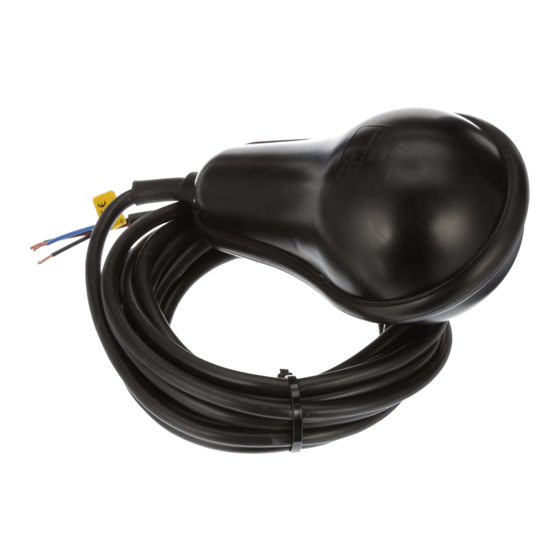
INTRODUCTION / TABLE OF CONTENTS Step One The LV41 Series Sump Float is a mercury‐free mechanically actuated floating switch intended to activate electrical components, usually pumps, to start and stop automatically. The LV41 series is perfect for simple level control of liquids for filling or draining reservoirs and tanks. Float switches such as the LV41 series are the most universally used for pump automation, due to their high reliability, economical pricing, and easy installation. ... -
Page 3: Specifications
Vertical Shipping Weight (housing): LV41: 5.43 oz (154 g) LV42: 2.4 lb (1100 g) Shipping Weight (cable): 0.77 oz (21.27 g) per foot Agency Approvals: Cautions FLOWLINE manufactures a wide range of liquid level switches and technologies. While each of these switches are designed to operate in a wide variety of applications, it is the user's responsibility to select a switch model that is appropriate for the application, install it properly, perform tests of the installed system, and maintain all components. The failure to do so could result in property damage or serious injury. 1. The pressure, temperature and electrical limitations shown for the specified level switches must not be exceeded. 2. The pressures and temperatures must take into consideration possible surges in the temperature and pressure of the system. 3. The liquids used must be compatible with the materials of construction. Specifications of materials will be given upon request. 4. Life expectancy of the switch varies with applications. 5. Ambient temperature changes can affect switch set points, since specific gravities of liquids vary with temperature. 6. Level switches have been designed to be shock and vibration resistant. For maximum life, both shock and vibration should be minimized. 7. Excessive contaminants in fluid may inhibit float operation, and occasional wipe down may be necessary. ... -
Page 4: Dimensions
DIMENSIONS Step Three LV41 Series Top View LV41 Series Side View LV42 Series Top View LV42 Series Side View 4 of 10 MN301200 Rev A ... -
Page 5: Safety
About this Manual: PLEASE READ THE ENTIRE QUICK START PRIOR TO INSTALLING OR USING THIS PRODUCT. This manual includes information on the Switch‐Tek LV41 and LV42 series sump floats from FLOWLINE. Please refer to the part number located on the switch label to verify the exact model configuration, which you have purchased. ... -
Page 6: Components
COMPONENTS Step Five Switch‐Tek sump floats are available in two different configurations with options for different lengths of cable. Depending on the model purchased, you may or may not have been shipped all the components shown below. Float o LV41‐7201 20’ of PVC cable Small Float o LV41‐7501 50’ of PVC cable Small Float o LV42‐7201 20’ of PVC cable Large Float o LV42‐7501 50’ of PVC cable Large Float Quick Start Guide Options/Accessories o Counterweight Part# LV49‐7000 o Cable Hanger Part# LV49‐9000 LV49‐7000 LV49‐9000 Shown Shown 6 of 10 MN301200 Rev A ... -
Page 7: Installation
INSTALLATION Step Five The basic operating principle of the sump float is very simple. As fluid level rises the float will also rise, resulting in a tilt of the micro‐switch located inside the housing. This tilt will generate a signal that can be used to actuate a motor or signal an indicator alarm. To ensure the proper function of the sump float, it is ... -
Page 8: Wiring
WIRING Step Five ELECTRICAL CONNECTIONS: The LV41 and LV42 series feature a SPDT relay contact. SPDT, single pole double throw allows for operation of both increasing and decreasing level, depending on the connections made between the terminals of the micro‐switch and the cable. SPDT, which is a three‐conductor cable, has one lead that is common, one that is normally open (NO), and the other that is normally closed (NC). For the proper connections of these conductors please refer to the wiring diagrams below. NC Wiring: The Normally Closed (NC) wiring is typically used for a filling operation. The contact will close at a low level ... -
Page 9: Maintenance
MAINTENANCE Step Six Maintenance should consist of inspection to see that the sump float is free to move and not coated with any substance, which would change its weight or volume significantly. If this occurs, the sump float should be cleaned. This is easily accomplished without disturbing the installation. Dents or nicks on the float are usually of no consequence to operation. Cleaning procedure: 1. Power: Make sure that all power to the sump float, controller and/or power supply is completely disconnected. ... -
Page 10: Warranty, Returns And Limitations
For complete product documentation, video training, and technical support, go to www.flowline.com. For phone support, call 562‐598‐3015 from 8am to 5pm PST, Mon ‐ Fri. (Please make sure you have the Part and Serial number available.) Warranty Flowline warrants to the original purchaser of its products that such products will be free from defects in material and workmanship under normal use and service in accordance with instructions furnished by Flowline for a period, which is equal to the shorter of one year from the date of purchase of such products or two years from the date of manufacture of such products. Flowline's obligation under this warranty is solely and ...
Need help?
Do you have a question about the Switch-Tek LV41 Series and is the answer not in the manual?
Questions and answers