Table of Contents

Related Manuals for FlowLine Switch-Tek LZ12 Series


Summary of Contents for FlowLine Switch-Tek LZ12 Series
- Page 1 Powered Liquid Level Switches LZ12, LU10, LP15 & LO10 Series Manual LZ12 Series LU10 Series LP15 Series LO10 Series Flowline, Inc. | 10500 Humbolt Street, Los Alamitos, CA 90720 p 562.598.3015 f 562.431.8507 w flowline.com MN301370 Rev B1...
-
Page 2: Table Of Contents
The switches all feature two outputs: 1) a 4 or 20 mA current switch and 2) a 60VA SPST dry contact relay. All four series are manufactured with thermoplastics, including the cable, making them submersible in design and ideal for corrosive applications. Package the switches with either Flowline controllers (LC10 or LC40 series) or interface directly to another controller or PLC. -
Page 3: Specifications
Specifications - Common Step Two COMMON SPECIFICATIONS Orientation: Universal Pressure: 150 psi (10 bar) @ 25 °C., Accuracy: ± 1 mm in water derated @ 1.667 psi (.113 bar) Repeatability: ± 0.5 mm in water per °C. above 25° C. Supply voltage: 12-36 VDC Sensor rating:... -
Page 4: Sensor Information
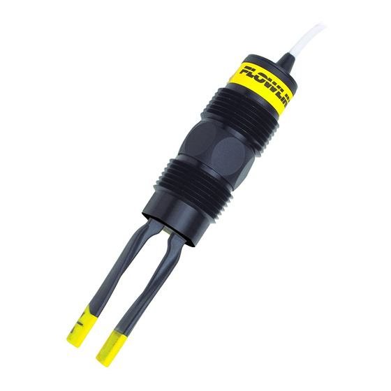
Sensor Information - Vibration Step Three VIBRATION LEVEL SWITCH (LZ12 SERIES) The Vibration switch operates at a nominal frequency of 400 Hz. As the switch becomes immersed in a liquid or slurry, a corresponding frequency shift occurs. When the measured frequency shift reaches the set point value, the switch changes state indicating the presence of a liquid or slurry medium. -
Page 5: Maintenance Alarm
Sensor Information - Vibration Step Three MAINTENANCE ALARM (LZ12 VIBRATION ONLY) For optimum performance and proactive maintenance, the sensor automatically adjusts for coating, and if necessary, outputs a preventative maintenance alarm. The Yellow wire is a NPN transistor designed to switch when a build-up of material prevents the vibration switch from operating at its operational frequency. -
Page 6: Ultrasonic Level Switch (Lu10 Series)
Sensor Information - Ultrasonic Step Three ULTRASONIC LEVEL SWITCH (LU10 SERIES) The Ultrasonic switch generates a 1.5 MHz ultrasonic wave from a miniature piezoelectric transducer located on one side of the gap within it’s sensing tip. Another piezo transducer, located on the other side of the gap, acts as a microphone, picking up the sound wave. -
Page 7: Optic Leak Detection Switch (Lo10 Series)
Sensor Information - Optic Step Three OPTIC LEAK DETECTION SWITCH (LO10 SERIES) The Optic switch use principles of optical refraction to detect the presence or absence of fluid. A pulsed infrared light beam is internally generated by a light emitting diode and aimed at the slanted optical tip of the sensor. -
Page 8: Capacitance Level Switch (Lp15 Series)
Stearic acid ....2.3 Chlorobenzene .. 4.7 to 6 ......11 to 17 Isobutyric acid ... 2.7 Toluene ..... 2.4 Note: Reference a website such as http://www.flowline.com for further dielectric information. LP15 SPECIFICATIONS Dielectric range: >20 constants Sensor material: Cable jacket mat’l: Conductive range: >100 miromhos... -
Page 9: Safety Precautions
PURPOSE SWITCH IN HAZARDOUS LOCATIONS. Warning The rating for the relay is 60 VA (125 VAC max / 1A max). Flowline’s Switch-Tek™ level switches are not recommended for use with electrically charged application liquids. For most reliable operation, the liquid being measured may need to be electrically grounded. -
Page 10: Installation
Smart Trak may be installed through the top wall of any tank using a standard 2" NPT tank adapter. If no tank top installation is available, Flowline's side mount bracket, LM50-1001, enables Smart Trak to be installed directly to the side wall of a tank. Do not use PFA Teflon sensors with Smart-Trak. -
Page 11: Electrical
Step Six SUPPLY VOLTAGE The supply voltage to the Switch-Tek™ level switch should never exceed a maximum of 36 VDC. Flowline controllers have a built-in 13.5 VDC power supply which provides power to all of Flowline’s electrically powered sensors. Alternative controllers and power supplies, with a minimum output of 12 VDC up to a maximum output of 36 VDC (30 VDC with LZ12 series), may also be used with the Switch-Tek™... -
Page 12: Wiring
Wiring Step Seven WIRING TO A FLOWLINE CONTROLLER LC40 Series Controller (4 or 20 mA output): LC10/LC11 Series Controller (4 or 20 mA output): LC42-1001 Shown LC11-1001 Shown SWITCHING INDUCTIVE LOADS The use of suppressors (snubbers) is strongly recommended when switching inductive loads to prevent disrupting the microprocessor’s operation. -
Page 13: Wiring The Relay Output
Wiring Step Seven WIRING THE RELAY OUTPUT Switch-Tek™ requires 12 - 36 VDC (30 VDC max. for LZ12 series) power to operate the sensor and switch the relay. All illustrations below identify a Dry switch state as the normal position of the relay. Switching a Normally Open DC Load Switching a Normally Closed DC Load The Red wire connects to Positive (+) of the power... -
Page 14: Intrinsically Safe Control Drawings (Lu10 Series Only)
SAFE APPLICATIONS. The Entity parameters for the LU10-_ _ _5 are: Vmax = 32 VDC / Imax = 0.5 A / Ci = 0 μF / Li = 0 mH INTRINSICALLY SAFE CONTROL DRAWING WIRING TO A FLOWLINE CONTROLLER LC90 Series Controller (4 or 20 mA Signal Output) LC90 Series... - Page 15 Wiring Step Seven LU10-_ _ _ 5 ULTRASONIC LEVEL SWITCH ONLY (CONTINUED) The LU10-_ _ _ 5 level switch has been approved for use in Class I, Division 1, Groups A, B, C & D; EEx ib IIC T6; UNDER CERTIFICATE NUMBER LCIE 01.E6048X. DO NOT USE THE LZ12, LP15 or LO10 SERIES IN INTRINSICALLY SAFE APPLICATIONS.
-
Page 16: Wiring As A P-Channel Or N-Channel Output
Wiring Step Seven WIRING AS A P-CHANNEL OR N-CHANNEL OUTPUT Switch-Tek™ level switch can be substituted for either a P-Channel (PNP, sourcing) output or an N-Channel (NPN, sinking) output. Normally Open DC Load as a P-Channel Output Normally Closed DC Load as a P-Channel Output The Red wire connects to Positive (+) of the power The Black wire connects to Positive (+) of the power supply and the Black wire connects to Negative (-). -
Page 17: Maintenance
Maintenance Step Eight GENERAL Switch-Tek™ level switches may require periodic cleaning to eliminate coating build-up. It is the responsibility of the user to determine the appropriate maintenance schedule, based on the specific characteristics of the application liquids. CLEANING PROCEDURE 1. Power: Make sure that all power to the switch, controller and/or power supply is completely disconnected. -
Page 18: Testing The Installation
Maintenance Step Eight TESTING THE INSTALLATION 1. Power: Turn on power to the controller and/or power supply. 2. Immersing the switch: Immerse the sensing tip in its application liquid, by filling the tank up to the switches point of actuation. An alternate method of immersing the switch during preliminary testing is to hold a cup filled with application liquid up to the switch's tip. -
Page 19: Warranty, Returns & Limitations
PERSON IS AUTHORIZED TO MAKE ANY OTHER WARRANTIES OR REPRESENTATIONS ON BEHALF OF FLOWLINE. This warranty will be interpreted pursuant to the laws of the State of California. If any portion of this warranty is held to be invalid or unenforceable for any reason, such finding will not invalidate any other provision of this warranty.
Need help?
Do you have a question about the Switch-Tek LZ12 Series and is the answer not in the manual?
Questions and answers