Table of Contents
Advertisement
Quick Links
Advertisement
Table of Contents

Related Manuals for FlowLine Smart Trak AU18-4343


Summary of Contents for FlowLine Smart Trak AU18-4343
- Page 1 w/ Compact Junction Box AU18, AU28, AU38, AU48, AV16, AV26, AV36, AV46, AZ18, AZ28, AZ38 & AZ48 Series Owner’s Manual Flowline, Inc. |. 10500 Humbolt Street, Los Alamitos, CA 90720. p 562.598.3015. f 562.431.8507. w flowline.com MN301420 Rev A...
-
Page 2: Specifications
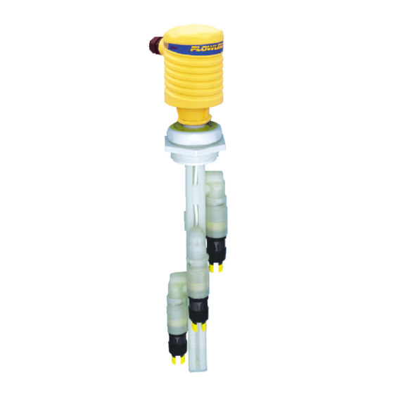
Specifications Step One Length: 8" to 10' (20 cm to 3m) Switch points: 1 t 4 (field adjustable) Orientation: ± 20˚ vertical Process temp.: F: -40˚ to 176˚ C: -40˚ to 80˚ Pressure: Atmospheric Wetted material: PP (20% glass fill) Process mount: 2"... - Page 3 Components Step Two ONE SENSOR CONFIGURATION: TWO SENSORS CONFIGURATION: (AU18-434_, AV16-434_ or AZ18-434_) (AU28-434_, AV26-434_ or AZ28-434_) Ultrasonic Buoyancy Vibration Ultrasonic Buoyancy Vibration AU18-4343 AV16-4343 AZ18-4343 AU28-4343 AV26-4343 AZ28-4343 1 x LU10-1305 1 x LV10-1301 1 x LZ12-1405 2 x LU10-1305 2 x LV10-1301 2 x LZ12-1405 1 x LM10-1_01...
-
Page 4: Safety Precautions
434_, AZ_8-434_ and AV_6-343_. The units are identical except for the number of switch points and the sensors technology. User's Responsibility for Safety: Flowline manufactures a wide range of liquid level sensors, controllers, and mounting systems. It is the user's responsibility to select components that are appropriate for the application, install them properly, perform tests of the installed system, and maintain all components. - Page 5 The track may be cut to length if desired. Four separate grooves run the length of the track, one on each side of the square. These grooves hold the sensor cars that attach to Flowline sensors, and also serve to contain the switch cable.
-
Page 6: Installation
Smart Trak™ may be installed thru the top wall of any tank or flange, using a standard 2" NPT tank adapter or blind flange. If tank top is not available, Flowline's side mount bracket, LM50- 1001, enables Smart Trak™... - Page 7 Installation Step Six SMART TRAK™, INSTALLATION: The Smart Trak™ with Compact Junction Box A key feature of Smart Trak™ is the adjustability of assembly is designed to be installed through a the level switches. When two level switches are 2” NPT (2” G) thread. The level switches will be placed close together, one of the switches will staggered through the fitting for installation.
- Page 8 Wiring Step Seven ULTRASONIC AND VIBRATION SWITCHES (LU10-1305, LU10-1325, LZ12-1405): The LU10-13_5 and LZ12-1405 switch can be wired normally open or normally closed for your application requirement. Each switch requires 12 - 36 VDC power (12-30 VDC, LZ12) to operate the sensor and switch the relay.
- Page 9 Wiring Step Eight BUOYANCY LEVEL SWITCH (LV10-1301 & LV10-1351): The LV10-13_1 switch can be wired normally open or normally closed for your application requirement. Normally Open: Normally Closed: Use the Black and White wires for operating the Use the Black and Red wires for operating the LV10-_3_1 in a normally open state.
- Page 10 Assembly of Smart Trak™ Step Nine SMART TRAK™ ASSEMBLY DRAWING (SIDE VIEW) Inventory: One Smart Trak™ kit (LM10-1__1) includes the following parts: 1 Seal Plug 1 Top compression fitting 1 Wire gasket 1 Thrust Plate 1 Locking pin 1 2" NPT fitting 1 Track 1 End cap SMART TRAK™...
- Page 11 Assembly of Switch Car™ Step Ten SENSOR CAR AND BAYONET ADAPTER: The sensor car assembly is the heart of the Smart Trak™ system. It slides in the grooves of the track, and is locked into position by a plastic bolt and screw. The bayonet to 3/4" NPT adapter has a female 3/4" NPT fitting on one end where the sensor (not included) will screw in, and a bayonet fitting on the other end that attaches it onto the sensor car with a slight turn, with an O-ring in-between to provide tension for the push-and-turn connection.
-
Page 12: Maintenance
Maintenance Step Eleven GENERAL: The Smart Trak™ with Compact Junction Box requires no periodic maintenance except cleaning as required. It is the responsibility of the user to determine the appropriate maintenance schedule, based on the specific characteristics of the application liquids. CLEANING PROCEDURE: 1. - Page 13 Maintenance Step Twelve CURRENT TEST (ULTRASONIC AND VIBRATION ONLY): Used to verify if the sensor is indicating a wet or dry condition. This test uses only two wires (Red and Black). The sensor draws 5 mA (ultrasonic) or 8 mA (vibration) when it is dry, and 19 mA when wet. The White and Green wires are not used.
-
Page 14: Warranty
PERSON IS AUTHORIZED TO MAKE ANY OTHER WARRANTIES OR REPRESENTATIONS ON BEHALF OF FLOWLINE. This warranty will be interpreted pursuant to the laws of the State of California. If any portion of this warranty is held to be invalid or unenforceable for any reason, such finding will not invalidate any other provision of this warranty.
Need help?
Do you have a question about the Smart Trak AU18-4343 and is the answer not in the manual?
Questions and answers