
Related Manuals for FlowLine Switch-Tek LV10-1301


Summary of Contents for FlowLine Switch-Tek LV10-1301
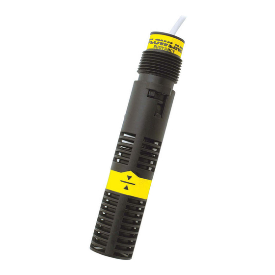
- Page 1 ™ Switch-Tek Vertical Buoyancy Liquid Level Switch LV10 Series Manual Flowline, Inc. | 10500 Humbolt Street, Los Alamitos, CA 90720 p 562.598.3015 f 562.431.8507 w flowline.com MN301340 Rev A2...
-
Page 2: Table Of Contents
Connection to a Switch Car Kit (LM30 series):: ........... 6 Electrical: ......................... 7 Smart Trak and Switch Pak Assemblies: ................ 7 Wiring: ..........................8 Wiring to a Flowline Controller: ..................8 Maintenance: ........................9 Warranty: ……………… ....................10 MN301340 Rev A2... -
Page 3: Specifications
Specifications / Dimensions Step Two Accuracy: ±2mm in water Switch Rating Repeatability: ±1mm in water Reed Maximum Orientation: ±20˚ from vertical Switch Resistive Specific Gravity: 0.8 minimum Rating Load Contact Type: (1) SPDT reed VA Volts Amps Amps Contact Rating: 15VA, 0.25A max. -
Page 4: Safety Precautions
User’s Responsibility for Safety: Flowline manufactures a wide range of liquid level switches and technologies. While each of the these switches are designed to operate in a wide variety of applications, it is the user’s responsibility to select a switch model that is appropriate for the application, install it properly,... -
Page 5: Installation
Step Four TOP WALL INSTALLATION FLOWLINE’s LV10 switch may be installed through the top wall of a tank. For Smart Trak (LM10 series) installations, remove the sensors thread and use the bayonet adapter to interface to the LM30 series Switch Car. -
Page 6: Connection To A Switch Car Kit (Lm30 Series)
Installation Step Four CONNECTION TO A SWITCH CAR KIT (LM30 SERIES) In order to attach the LV10 series to a Smart Trak (LM10 series) fitting, a Switch Car Kit (LM30 series) is required. The LV10 series can be attached in two ways, without the bayonet adapter and with the bayonet adapter. -
Page 7: Electrical
The input voltage to the LV10 switch should never exceed the maximum voltage rating. FLOWLINE controllers have a built-in 13.5 VDC power supply which provides power to all of FLOWLINE’s level switches. Alternate controllers and power supplies may also be used with the LV10 switch. -
Page 8: Wiring
Wiring Step Seven WIRING TO A FLOWLINE CONTROLLER LC40 Series Controller (LC42-1001 Shown) LC10/LC11 Series Controller (LC11-1001 Shown) NOTE: When using a latching relay, the polarity of both switches must be the same. Either both switches are wired Normally Closed (Red & Black – See Relay #2 with LC42) or both Normally Open (White & Black – See Relay #1 with LC11). -
Page 9: Maintenance
Maintenance Step Eight GENERAL While a filter should protect the float from particulate contamination, the switch may need to be cleaned periodically to prevent jamming of sticking. The vertical buoyancy and vertical float has no scheduled maintenance requirement, except to clean off any deposits or scaling from the switch as necessary. It is the responsibility of the user to determine the appropriate maintenance schedule, based on the specific characteristics of the application liquid. -
Page 10: Warranty
PERSON IS AUTHORIZED TO MAKE ANY OTHER WARRANTIES OR REPRESENTATIONS ON BEHALF OF FLOWLINE. This warranty will be interpreted pursuant to the laws of the State of California. If any portion of this warranty is held to be invalid or unenforceable for any reason, such finding will not invalidate any other provision of this warranty.
Need help?
Do you have a question about the Switch-Tek LV10-1301 and is the answer not in the manual?
Questions and answers