Advertisement
Quick Links
Advertisement

Related Manuals for FlowLine EchoPod DL10 Series


Summary of Contents for FlowLine EchoPod DL10 Series
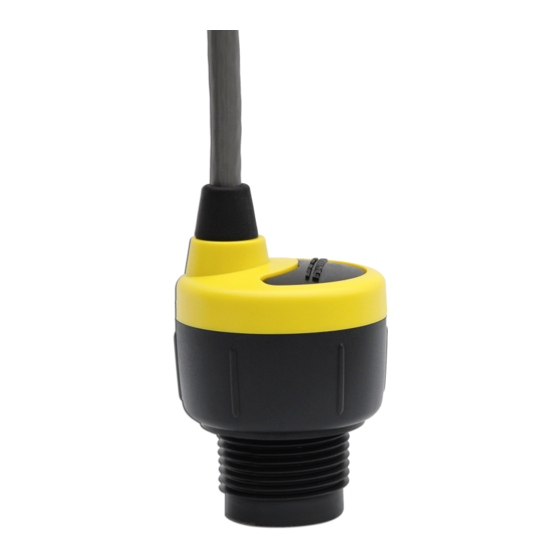
- Page 1 Ultrasonic Level Switch, Controller & Transmitter DL10, DL14, DL24, DS14 & DX10 Series Quick Start DL14-00 Shown ©2016 Flowline, Inc. All Rights Reserved Made in USA Flowline, Inc. | 10500 Humbolt Street, Los Alamitos, CA 90720 p 562.598.3015 f 562.431.8507 w flowline.com QS204210 Rev C...
- Page 2 If you have a non-standard installation or setup requirement that is not addressed here, ® please refer to the EchoPod Manual or support documentation at flowline.com. WE DO YOUR LEVEL BEST™ ® Thank you for purchasing EchoPod .
- Page 3 , please refer to the WebCal ® manual located at flowline.com/webcal-software, or contact a Flowline applications engineer at (562) 598-3015. 1. Output Configuration a. Defines the relay pump, valve or alarm and/or output operational settings. b. Defines the relay and output (current, voltage or frequency) fail-safe settings.
-
Page 4: Output Configuration
2. Volumetric Configuration a. To configure in volume versus distance (factory default), defines the tank shape and dimensional information with respect to the sensor’s location on the tank. 3. Tank Level Configuration a. Defines the relay activation and output operational set points. 4. - Page 5 Volumetric Configuration Defines the shape of the tank as well as the dimensional information for the tank with respect to the sensor’s location on the tank. Note: This section is only used when changing the sensor configuration units from the factory default of distance (liquid height in inch, cm, feet or meter) to volume (liquid in gallons or liters).
- Page 6 Tank Level Configuration Enter the settings for the relay activation points and operational range. Complete the Configuration Use the buttons on the right side of the WebCal ® screen to complete the configuration. QS204210 Rev C...
- Page 7 Changing these setting will alter the factory default performance and operation of your sensor. Please read the Help file to assist you in making adjustments, or if you are unclear about a specific issue, please contact a Flowline applications engineer at (562) 598-3015. Increase Output Filtering: Placing a check mark •...
- Page 8 Installation in Open Tanks or Sumps: Use Flowline's • LM52-2890 LM50-1001-1 side mount bracket. Note: The bracket is not designed for use with stand-pipes.
-
Page 9: Stand-Pipe Installation
Mounting Guidelines 1. Never mount the sensor at an angle. 2. Liquid should never enter the sensor dead band. 3. Mount the sensor at least 2” from the side wall. 4. Never mount the sensor in a vacuum. 5. Do not obstruct the sensor beam width. Stand-Pipe Installation A stand-pipe may be used to dampen turbulence, separate surface foam from the point of measurement or increase performance in heavy vapor. - Page 10 WIRING ECHOPOD ® After mounting the sensor, make the necessary electrical connections. A wiring diagram with specific recommendations for the sensor’s configuration can be printed from the WebCal ® program. A typical wiring diagram is shown on the next page. DL14, DL24 &...
- Page 11 Typical Wiring Diagram Sample Wiring Diagram The diagram will change based upon the sensor’s configuration. Use WebCal to view appropriate ® wiring diagram. Electrical Connections, Usage and Safety Where personal safety or significant property damage can occur due to a spill, the installation must •...
-
Page 12: Warranty
WARRANTY Flowline warrants to the original purchaser of its products that such products will be free from defects in material and workmanship under normal use and service in accordance with instructions furnished by Flowline for a period of two years from the date of manufacture of such products. Flowline's obligation under...
Need help?
Do you have a question about the EchoPod DL10 Series and is the answer not in the manual?
Questions and answers