Table of Contents
Advertisement
Quick Links
Version 1.8 September 2022
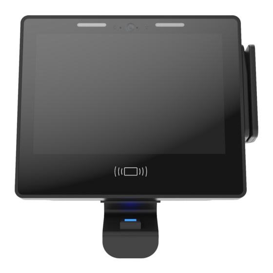
GT10 Terminal
User Guide
Disclaimer
Copyright 2022, Grosvenor Technology Ltd. All rights reserved.
All brands, names, or trademarks appearing in this document are acknowledged as the
trademarks of their respective owners.
No part of this document may be reproduced in any form or by any means for any purpose without
the written permission of Grosvenor Technology.
Whilst we make every effort to ensure the accuracy of our publications, Grosvenor Technology
assumes no responsibility or liability for any errors or inaccuracies that my appear in this
document.
Advertisement
Table of Contents

Related Manuals for Grosvenor GT10


Summary of Contents for Grosvenor GT10
- Page 1 No part of this document may be reproduced in any form or by any means for any purpose without the written permission of Grosvenor Technology. Whilst we make every effort to ensure the accuracy of our publications, Grosvenor Technology assumes no responsibility or liability for any errors or inaccuracies that my appear in this...
-
Page 2: Table Of Contents
About the GT10 terminal ........ - Page 3 Contents Camera ............2-3 Physical Security .
- Page 4 Contents Battery backup ..........5-2 Fitting the battery pack .
- Page 5 Accessing the GT10 terminal ........
- Page 6 Contents Deployment........... . . 11-2 Deployment from USB memory device .
- Page 7 Chapter 1: Preface...
- Page 8 Preface Important Note: Menus and options will vary depending on the hardware options supplied and software version installed. Please refer to additional instructions supplied with your terminal for additional information. Page 1-1...
-
Page 9: Preface
This GT10 User Guide is intended for users who will be responsible for installing and configuring the GT10 terminal. It is aimed at users who need to understand how to configure the terminal, remotely connect to the terminal and how to install applications onto the terminal. -
Page 10: Technical Support
Preface Technical Support Technical Support can be obtained from Grosvenor Technology from the following points of contact: Europe, Middle East and Africa Phone: +44 (0)1202 627611 E-mail: HCM-EMEAsupport@grosvenortechnology.com Website: www.grosvenortechnology.com North America Phone: +1 800.989.5197 E-mail: HCM-USsupport@grosvenortechnology.com Website: www.gtclocks.com... -
Page 11: Hardware Specification
Chapter 2: Hardware specification... -
Page 12: Terminals
Hardware specification Terminals Front Panel Assembly FP-GT10-2A Display 10 inch full colour capacitive multi-touch display with toughened glass for use in high traffic environments 16:9 aspect ratio, 1280 x 800 pixel resolution Processor Industrial specification ARM Cortex A9 Quad Core 800MHz ... -
Page 13: Temperature Screening Module
Hardware specification Temperature Screening module Modules Temperature Screening module EM-TM-X Temperature Module Mounting Kit - GT10 EM-TM-KIT-A Expansion modules IO Relay Module EM-IO-USB-IT IO External Reader Relay Module EM-IO-ER-IT Memory 2GB RAM Internal Persistent Storage 8GB high performance flash storage ... -
Page 14: Integration
Hardware specification Integration Supports native Android and HTML 5 Apps Software Development Kit available Sound 2x Integrated stereo speakers Integrated microphone Camera 5 mega-pixel IR camera, wide angle; supports photo and video Physical Security Lockable case ... - Page 15 Hardware specification Power over Ethernet (PoE). Built in module enables terminal to be powered via the Ethernet cable using IEEE802.3af or IEEE802.3at Ethernet switch or mid-span injector. Note: it is strongly recommended that POE+ (IEEE802.3at) is used to ensure that there is sufficient power available for the terminal.
-
Page 16: Opening And Fitting Front Panel To Back Panel
Note: the key cannot be removed in the unlocked position The GT10 terminal can be customised by fitting a range of option modules. Internal Proximity Reader Modules For reading credentials including cards and tags: ELATEC Reader Module RM-ELATEC-A ... -
Page 17: Card Swipe Reader Modules
Hardware specification Card Swipe Reader Modules Barcode Reader Module RM-BAR-A Magnetic Stripe Reader Module RM-MAG-A RM-BARV-A Barcode Visible Swipe Reader Biometric Modules RM-SP-SFSLIM-GT10A Page 2-6... - Page 18 Chapter 3: Software...
- Page 19 Software Operating System Android 6.0 Supports native Android and HTML 5 Apps Remotely upgradeable/configurable Page 3-2...
- Page 20 Chapter 4: Installation...
- Page 21 Chapter 4: “Power options” . The environment the GT10 will be installed into, if the GT10 is to be installed in an outdoor, wet, harsh or extreme environment then the AE-ENC-EP-GT10 environmental protection enclosure should be used to protect the GT10.
-
Page 22: Fitting The Terminal
Installation Fitting the terminal Location The terminal should be fixed to a flat surface at a height that is comfortable for users to view and interact with the screen without glare from reflections and in a suitable level of ambient light. Take care to adhere to any local regulations such as disabled access when determining the height of the unit. -
Page 23: Face Recognition
Installation Face recognition Note : face recognition is only available if your application supports it The face recognition application recognises enroled employees using facial recognition algorithms that allow the detection and recognition of individuals using facial characteristics: such as measurements of eyes, nose, mouth and ears. Our facial recognition is also compatible with Mask Detection and prevents payroll fraud or ‘buddy punching’. -
Page 24: Enrolment
DO NOT use any other cleaning products, such as: acids, solvents, polishes or abrasives. Enrolment When the GT10 has been installed, employees then need to have their image taken and enroled. During enrolment the employee must ensure that the image taken: Contains no other people or objects ... -
Page 25: Supporting Information And Faqs
Installation Supporting Information and FAQs Q. Should an employee who wears glasses enrol with or without them on? A. If the employee wears glasses, for best results, we would recommend enrolling with glasses on. Employees should do their best to prevent glare on the glasses during the enrolment process Q. -
Page 26: Power Options
Chapter 5: Power options... -
Page 27: Ac 110-240V Via Adapter
Note: it is strongly recommended that POE+ (IEEE802.3at) is used to ensure that there is sufficient power available for the device. When the GT10 is running from PoE the power indicator on the front of the device is blue. Page 5-1... -
Page 28: Battery Backup
0% to 100% will range from three hours to 12 hours. Charging times will be extended in elevated ambient temperatures to protect the battery. When the GT10 is running from battery the power indicator on the front of the terminal will show red. -
Page 29: Fitting The Battery Pack
Power options Fitting the battery pack The EM-BB-2HR-A battery pack comprises a rechargable li-on battery along with protection circuitry to prevent safety hazards caused by overload, over-charging or over-discharge. WARNING: ONLY FIT THE BATTERY PACK SPECIFIED. FAILURE TO OBSERVE MAY RESULT IN FIRE HAZARD Service life of the EM-BB-2HR-A battery pack is typically up to three years, depending on conditions and regular replacement is recommended. -
Page 30: Installing Option Modules
Chapter 6: Installing option modules... -
Page 31: Front Panel Fitted Options
Note : you may find it easier to refit the lower cover with the battery removed and then fit the battery afterwards, ensuring the battery retaining clip pops out to secure the battery in place. Reader Module options The GT10 is compatible with the following Reader modules, each of which is described in this chapter: Reader Module name... -
Page 32: Card Swipe Reader Modules
Installing option modules Card Swipe Reader Modules Barcode Reader module RM-BAR-A Magnetic Stripe Reader module RM-MAG-A Barcode Visible Swipe Reader RM-BARV-A Fitting Swipe Reader Modules To fit the Swipe Module, remove the front panel and place face down on a clean flat surface that will not scratch the glass front. - Page 33 Installing option modules Insert the tabs on the reader module into the front panel, pressing down until the tabs are fully inserted. Then, slide the module so there is no gap between the side of the module and the front panel bezel. Screw down the two fixing screws to secure the module.
-
Page 34: Barcode Visible Swipe Reader (Rm-Barv-A) & Barcode Ir Swipe Reader (Rm-Bar-A)
Installing option modules Barcode Visible Swipe Reader (RM-BARV-A) & Barcode IR Swipe Reader (RM-BAR-A) The RM-BAR-A (IR) / RM-BARV-A (Visible) is a barcode swipe reader module for data collection terminals. Reads IR and most Visible barcodes Auto detects barcode symbology ... -
Page 35: Magnetic Swipe Reader (Rm-Mag-A)
The Reader Test Screen displays the badge output. Magnetic Swipe Reader (RM-MAG-A) The RM-MAG-A is a swipe reader module for reading magnetic stripe cards with data collection terminals including GT10. Standard Clock and Data output Reads cards encoded to ISO 7811 in either direction ... -
Page 36: Elatec Reader Module (Rm-Elatec-A)
Typical read range, depending on card technology, 40mm with ISO card and 20mm with Easy to fit - no wiring required Customisable and automatic configuration when used in GT4, IT51 and GT10 Can be configured to read multiple card technologies ... -
Page 37: Configuring The Reader
Installing option modules Configuring the Reader The Elatec Reader Module can be configured to read different card technologies and badge formats by creating a new policy file and sending to the terminal using AssistIT or via a USB memory stick. For further information on creating the config files and loading into the reader, please refer to the Elatec documentation and AssistIT User Guide. -
Page 38: Hid Iclass Se Reader Module (Rm-Iclse-It/Rs)
Installing option modules HID iClass SE Reader Module (RM-ICLSE-IT/RS) The RM-ICLSE-IT/RS / RM-ICLSE-LH-IT/GT is an internal proximity card reader for HID 125kHz cards and tags. The modules can be used in basic mode where the iClass credential number is output in serial or Wiegand format or as a reader/writer using a serial interface (subject to terminal software): Standard Wiegand output compatible with previous versions... -
Page 39: Deister Reader Module (Rm-Dei-It/Rs)
Installing option modules Deister Reader Module (RM-DEI-IT/RS) The RM-DEI-IT/RS is an internal proximity card readers for Deister 125kHZ cards and tabs. Ribbon Connector Mounting screws Mounting screws For information on how and where to fit the Reader Module, see page 6-14. Feig Fixed Code Reader Module (RM-FEIG-FC-IT/RS &... -
Page 40: Reader Mounting Plates (Rmk-5Vprx-It/Rs) And (Rmk-12Vprx-A)
12V Reader Mounting Plate (RMK-12VPRX-A). This Reader Mounting Plate is used to connect readers which require a 12 Volt supply and is for the GT10 terminal. The Mounting Plate PCB supports readers that have Wiegand or Clock & Data type outputs. A four-way screw terminal block is used to interface the reader. - Page 41 Installing option modules A Reader Mounting Plate PCB along with its mounting spacers/screws are displayed below: Where it is possible to mount the reader directly on the RMK mounting plate PCB, the appropriate length of spacer should be selected to ensure the reader is located as close as possible to the inside of the front cover.
-
Page 42: Suprema Sfslim Ident 10K Reader Module (Rm-Sp-Sfslim-Gt10A)
Installing option modules Suprema SFSlim Ident 10K Reader Module (RM-SP-SFSLIM-GT10A) The Suprema SFSlim Ident 10K Reader Module is a high performance fingerprint Reader Module capable of both verification and identification. Large 22,000 finger template capacity (two templates stored per finger enrollment). ... -
Page 43: Testing The Module And Software
Installing option modules Put the USB cable through the hole and slide the Reader Module into position. The Reader Module comes with three screws. The two longer screws are used to secure the outer edge of the Reader Module and the smaller screw is used in the middle. -
Page 44: Fitting Internal Proximity Reader Modules
Mounting position supplied with the module. Connect the reader module Fix screws in module to Tighten screws until ribbon cable to the GT10 threaded bushes in front module is firmly fixed READER 1 connector panel with cable tucked but take care to not over... -
Page 45: Fitting The Power Over Ethernet Module
Installing option modules Fitting the power over Ethernet module Part no: CM-POE-HC-IT The fitting position for the PoE is displayed in red: Manoeuvre the module into position as displayed. Press the module down until it clicks into place on the three mounting pillars. Page 6-15... -
Page 46: Removing The Poe Module
Installing option modules Removing the PoE module Use a flat blade screwdriver to lever the module, as displayed to release the top fixing. Reposition the screwdriver and fully release the module. Page 6-16... -
Page 47: Fitting The Wi-Fi Module
Installing option modules Fitting the Wi-Fi module The fitting position for wi-fi module and antennae is illustrated below. Fit the module as illustrated below to socket JP4 and secure with screws. Fit the two antennae to the case. These are secured with loop and hook fastening, the loop part is fitted to the front panel during manufacture in the two antenna locations. -
Page 48: Temperature Screening
The Temperature Screening module can be installed on either an Android GT10 and connects via the USB, using the appropriate kit. The Temperature Screening module is available as a production and post production add-on. For post-production customers, please refer to the Temperature Screening module Guide for complete installation instructions. -
Page 49: Cleaning
Installation Safety The Temperature Screening module should be installed in accordance with the instructions documented in the Temperature Screening module User Guide. The GT10 Temperature Screening module should be installed in compliance with any Health and Safety legislation and it is recommended that any electrical or network connections to the terminal are undertaken by a suitably qualified engineer. -
Page 50: Temperature Screening Module Performance Specifications
Installing option modules Temperature Screening module performance specifications Feature Specification Camera Micro thermal imaging device ° Temperature accuracy +/- 0.5 Interface Ambient light Device should be positioned so that it is not exposed to direct sunlight which may affect the operation of the sensor Ambient temperature Normal ambient operating temperature should be between °... - Page 51 Chapter 7: System start-up...
- Page 52 System start-up When the GT10 system is powered on, a bootloader runs which loads the Android operating system. This runs start-up scripts to set up and configure the terminal and to start enabled services. When an application is installed and once the unit is fully booted, the initial screen gives you the opportunity to enter the Terminal Setup.
-
Page 53: Terminal Setup
Chapter 8: Terminal setup... -
Page 54: Accessing The Gt10 Terminal
Terminal setup Accessing the GT10 terminal The set-up menus allow the terminal configuration to be changed at the terminal. To access the Terminal setup Settings menu, allow the terminal to boot and then click Admin. A PIN is required to enter setup mode: the default is 1905. From the Apps menu, click settings. -
Page 55: Configuring Network Settings
When you select Wi-Fi, the wireless must be activated to see available networks. Configuring Readers The GT10 accommodates a wide range of reader types and credential format. There are two elements: Reader type. This relates to the reader hardware and its connection to the system: for ... -
Page 56: Reader Configuration
Terminal setup Reader configuration The options displayed vary on the reader type. Readers are categorised as Proximity of Swipe, with sub sections within each category, for individual reader types. Wiegand Bitmask In addition to the standard fixed decodes for reader data a configurable bit mask can be applied to create custom decodes. -
Page 57: Parity Mask
Terminal setup Mask char Description Signifies parity bit (ignored here) Bit is ignored Bit is ignored The characters ‘P’, ‘.’ and ‘X’ are all ignored when parsing bitmasks. As the length of the bitmask has to match the number of bits, it is sometimes useful to be able to specify more than one bitmask. -
Page 58: Testing Readers
Terminal setup Testing readers The GT10 includes a utility to display the output of a reader to validate correct functionality and setup for readers. The utility is accessed from the Readers & peripherals dialog. Page 8-5... -
Page 59: Terminal Health Information
Terminal setup Terminal health information The GT10 monitors key elements of the system and can display their status. To do this, from the Settings menu, click Health. From the Health screen, select an item to display further information: such as, voltages, currents and detailed status information for the hardware that is installed in the unit. -
Page 60: System Shutdown
Chapter 9: System shutdown... - Page 61 When the GT10 has the battery backup option installed the unit will continue to run following a power failure until the battery capacity reaches a low threshold where the graceful shutdown will be triggered.
-
Page 62: Terminal Recovery
Chapter 10: Terminal recovery... -
Page 63: Software Reset
Terminal recovery Software reset Android provides a mechanism to remove installed packages and data from the device. To do this, under Settings, click Backup & reset and click then click Factory data reset. Recovery menu To access the Recovery menu options, press and hold the Recovery, whilst the terminal. is powering up. -
Page 64: Software Update Service
Chapter 11: Software Update Service... -
Page 65: The Software Update Service Application
The firmware and packages can be updated automatically, based on policy, and so on, via the software updates application. The service also provides methods for easy provisioning and deployment via network or USB. For detailed information regarding the Software Update Service, please contact Grosvenor Technology. The software Update Service application... -
Page 66: Repository
The auto-update feature also operates with an update policy, that enumerates which type of updates it can install: for example, bug-fixes only, minor changes or always the latest. For more information on the Repository file format, please contact Grosvenor Technology. Deployment Deployment is the process of configuring an unconfigured terminal with all required application packages and settings. -
Page 67: Deployment From Network
Software Update Service Deployment from network Deployment from network allows to easily configure a specific update repository, see “Repository” on page 11-2 and install all packages from it. You only need to enter an ID and PIN which is combined with the base URL to access the repository. -
Page 68: Care And Maintenance
Chapter 12: Care and maintenance... -
Page 69: Maintenance Instructions
DO NOT use any other cleaning products, acids, solvents, polishes or abrasives. As long as the care instructions for the GT10 are followed, there is no need for regular maintenance of the terminal (other than the battery). Page 12-1...
Need help?
Do you have a question about the GT10 and is the answer not in the manual?
Questions and answers