Table of Contents
Advertisement
Quick Links
Version 1.6 March 2022
GT8 Terminal
User Guide
Disclaimer
Copyright 2022, Grosvenor Technology Ltd. All rights reserved.
All brands, names, or trademarks appearing in this document are acknowledged as the
trademarks of their respective owners.
No part of this document may be reproduced in any form or by any means for any purpose without
the written permission of Grosvenor Technology.
Whilst we make every effort to ensure the accuracy of our publications, Grosvenor Technology
assumes no responsibility or liability for any errors or inaccuracies that my appear in this
document.
Advertisement
Table of Contents

Related Manuals for Grosvenor GT8


Summary of Contents for Grosvenor GT8
- Page 1 No part of this document may be reproduced in any form or by any means for any purpose without the written permission of Grosvenor Technology. Whilst we make every effort to ensure the accuracy of our publications, Grosvenor Technology assumes no responsibility or liability for any errors or inaccuracies that my appear in this...
-
Page 2: Table Of Contents
About the GT8 terminal ........ - Page 3 Fitting GT8 to wall bracket ........
- Page 4 GT8 IO Relay boards ........
- Page 5 Contents Terminal shut down Software reset ..........7-2 Recovery menu .
- Page 6 Chapter 1: Preface...
- Page 7 Preface Important Note: Menus and options will vary depending on the hardware options supplied and software version installed. Please refer to additional instructions supplied with your terminal for additional information. Page 1-2...
-
Page 8: Preface
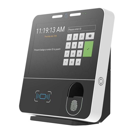
Preface About the terminal The GT series of data collection terminals has been designed for various applications including Time and Attendance in both the commercial and retail sectors, where low cost, flexibility and ease of installation are essential factors. The terminal incorporates a flexible, modular hardware design which supports different reader technologies such as biometric, proximity, barcode and magnetic as well as enabling power supplies and ancillary input/output modules to be easily added. -
Page 9: Certifications
The GT8 is also fitted with a button cell type battery on the main PCB to maintain the real-time clock (RTC) of the device when power is removed. This battery typically has a service life of around 10 years. -
Page 10: Cleaning
Installation Safety The GT8 terminal should be installed in accordance with the instructions documented in this User Guide. The terminal should be installed in compliance with any Health and Safety legislation and it is recommended that any electrical or network connections to the terminal are undertaken by a suitably qualified engineer. -
Page 11: About The Gt8 Terminal
Preface About the GT8 terminal GT8 is more than just a next generation time and attendance terminal - it’s designed to open up a world of possibilities for wider integration with Human Resources Management Systems (HRMS) and a myriad of potential new applications beyond workforce management. -
Page 12: Hardware Specification
Chapter 2: Hardware specification... -
Page 13: Terminals
Hardware specification Terminals Front Panel Assembly - Black FP-GT8-BL Front Panel Assembly - White FP-GT8-WH Display 8 inch full colour capacitive multi-touch display with toughened glass for use in high traffic environments 16:10 aspect ratio, 1280 x 800 pixel resolution ... -
Page 14: Temperature Screening Module
Hardware specification Temperature Screening module Modules Temperature Screening module EM-TM-X Temperature Module Mounting Kit - GT8 EM-TM-KIT-B Expansion modules IO Relay Module EM-IO-RLY-B IO External Reader Relay Module EM-IO-ER-B Memory Internal Persistent Storage 16GB high performance flash storage ... -
Page 15: Plug And Play
Hardware specification Plug and Play Fast easy installation Easy to fit reader modules and peripherals VESA mount fixings Integration Supports native Android and HTML 5 Apps Software Development Kit available Sound Integrated stereo speakers ... -
Page 16: Reader Modules
Swipe Reader Module Mag, Barcode Visible & IR Prox Reader Module Or custom logo with illumination The GT8 terminal can be customised by fitting a range of optional modules Reader modules Barcode Reader Module Infra Red RM-BAR-B Barcode Reader Module Visible RM-BARV-B ... - Page 17 Hardware specification 125KHz Reader Module RM-HID-B iClass SE Reader Module RM-ICLSE-B Elatec MultiTech Reader Module RM-ELATEC-B Feig HI Reader Module RM-FEIG-HI-B Feig FC Reader Module RM-FEIG-FC-B Barcode Visible Red Reader Module RM-BARV-B Barcode Infra Red Reader Module RM-BAR-B ...
- Page 18 Hardware specification Camera Module Accessory Mounting Battery Connector JP4 Socket Reset Button Battery Location Dotted line RTC Backup Battery Micro USB Connector Stereo Speakers One each side Swipe Reader Module Connector Power IN Recovery button Connector (2.1mm) USB Connector BIO Module Location Ethernet Connector Connector...
-
Page 19: Comms Modules
Hardware specification Battery connector. For connection of the GTL Li-Ion Battery Pack EM-BB-2HR-A Provides up to 2 hour runtime Battery backup may be used with all power options including PoE Note: units are shipped with battery disconnected. Please connect battery before first use (tuck wires into space at side of battery to avoid obscuring Power IN Connector WARNING: only fit battery pack specified, failure to observe may result in fire hazard Battery location. -
Page 20: Installation
Chapter 3: Installation... -
Page 21: Fitting The Terminal
Note : before fitting, please check local regulations such as disabled access when determining the height of the unit Cable routing The GT8 provides a number of cable routing options, as displayed below. For ease of cable routing, we highly recommend using the lower (larger) aperture, where possible. Page 3-1... -
Page 22: Fitting Gt8 To Wall Bracket
With the terminal fully down until it stops against the wall bracket re-fit Offer the GT8 unit close to the the M4 screw in the base making wall bracket and connect sure to press the lower portion of the Ethernet and/or power cables. -
Page 23: Face Recognition
Installation Face recognition Note : face recognition is only available if your application supports it. The face recognition application recognises enroled employees using facial recognition algorithms that allow the detection and recognition of individuals using facial characteristics: such as measurements of eyes, nose, mouth and ears. Our facial recognition is also compatible with Mask Detection and prevents payroll fraud or ‘buddy punching’. -
Page 24: Enrolment
DO NOT use any other cleaning products, such as: acids, solvents, polishes or abrasives. Enrolment When the GT8 has been installed, employees then need to have their image taken and enrolled. During enrolment the employee must ensure that the image taken: Contains no other people or objects ... -
Page 25: Supporting Information And Faqs
Installation Supporting Information and FAQs Q. Should an employee who wears glasses enrol with or without them on? A. If the employee wears glasses, for best results, we would recommend enrolling with glasses on. Employees should do their best to prevent glare on the glasses during the enrolment process Q. -
Page 26: Power Options
Chapter 4: Power options... -
Page 27: Ac 110-240V Via Adapter
Power options AC 110-240V via adapter The GT8 terminal can be powered from an AC power outlet using an optional plug-top or wall wart power supply. Adapters include: AE-PSU-PT-12VDC universal adapter with UK, Europe, Australia and US interchangeable ... -
Page 28: Battery Backup
Power options Battery backup As standard the GT8 is fitted with a backup battery (EM-BB-2HR-A) to run the terminal should the normal power supply fail, providing up to 2-hours runtime. When the battery pack is installed the terminal will continue to run when power is removed until the battery charge level reaches its lower threshold. - Page 29 Power options Battery Connector For connection of the GTL Li-Ion Battery Pack EM-BB-2HR-A Provides up to 2 hour run time Battery backup may be used with all power options including PoE Note: units are shipped with battery disconnected. Please connect battery before first use (tuck wires into space at side of battery to avoid obscuring Power IN Connector) WARNING: only fit battery pack specified.
-
Page 30: Installing Optional Modules
Chapter 5: Installing optional modules... -
Page 31: Front Plate
For information on how to fit the Temperatures Screening module, refer to the Temperature Screening module User Guide. Front plate Depending on the option chosen the GT8 lower glass front plate may be either. With fingerprint aperture. Without fingerprint aperture. -
Page 32: Reader Module Options
Installing optional modules Reader module options The GT8 is compatible with the following Reader modules, each of which is described in this chapter: Page Reader Module name Reader module code reference Barcode Reader Module Infra Red RM-BAR-B page 5-4... -
Page 33: Fitting Internal Fingerprint Reader Module
Installing optional modules Fitting internal fingerprint reader module RM-SP-SFSLIM-GT8 Note: the fingerprint reader module is normally a factory fit option only USB connection Remover lower cover. Slide fingerprint reader module under the PCBA, ensuring ribbon cable does not detach. Secure with screws provided (do not over tighten). -
Page 34: Fitting Swipe Reader Modules
Note : proximity and card swipe readers use the same mounting location, only one internal module may be fitted to the GT8 at the same time. When fitting swipe card readers, ensure the reader head is located correctly in the aperture at the bottom of the GT8 before fully securing using the screws supplied. - Page 35 Installing optional modules Fitting Proximity Reader Modules RM-HID-B and RM-ICLSE-B RM-HID-B and RM-ICLSE-B Proximity Reader & card swipe mounting position Remove lower cover. Position proximity/card swipe module and secure with screws provided (do not over tighten). Connect ribbon cable to connector on PCBA, circled in the diagram on the right.
-
Page 36: Fitting The Wi-Fi Module
Tip: You may need to press down lightly on the module to make fitting the securing screw easier. Applying light pressure, attach antennae to the fabric strips on the sides of the GT8 terminal. The fabric strips are attached during manufacture and are not supplied separately. -
Page 37: Gt8 Io Relay Boards
USB ports. The GT8 terminal has optional I/O relay modules that can be installed via the USB ports in the back of the terminal. There are two modules available offering either a single relay output/single input or a dual relay output/dual input module, which also provides Wiegand and external reader connections. -
Page 38: The Em-Io-Rly-B Relay Board
Installing optional modules The EM-IO-RLY-B Relay board Status Indicator LEDs IP1 Input 1 ON LED RLY1 Output 2 Relay Energised LED Relay Out - 3A max 1 Common 1 2 Normally Open 1 3 Normally Closed 1 The EM-IO-RLY-B is an expansion module which provides relay outputs and auxiliary inputs: Single relay output. - Page 39 IO PCB. To test the Relay board, from the GT8 terminal, do the following: From the Home screen, click Admin.
- Page 40 Installing optional modules Click Readers & peripherals. Click IO board information. Page 5-10...
- Page 41 The relay LED on board lights up The orange light denotes the relay is energised. If you short the Input to ground, the Input LED is illuminated, GT8 terminal display IO Relay board The relay LED on board lights up Replace the lower cover.
-
Page 42: The Em-Io-Er-B Relay Board
Installing optional modules The EM-IO-ER-B Relay board The EM-IO-ER-B is an expansion module which provides additional facilities to the basic GT8 front panel: Connection for External Card Reader (Wiegand or Clock and Data) Two Auxiliary inputs Two relay outputs (3 Amp capability) ... - Page 43 Rubber foot If a rubber foot has been attached to the terminal, remove it. Insert the Relay board into two USB ports. To test the Relay board, from the GT8 terminal, do the following: From the Home screen, click Admin.
- Page 44 Installing optional modules Enter PIN (the default is 1905) and click From the Apps screen, click Settings. Click Readers & peripherals. Click IO board information. Page 5-14...
- Page 45 The RLY 1 and RLY 2 orange LEDs are lit to denote the relays are energised. If you short the Input 1 or 2 to ground, the corresponding Input LED is illuminated, GT8 terminaldisplay IO Relay board The relay LED on board lights up...
-
Page 46: Temperature Screening
The Temperature Screening module can be installed on either an Android GT8 or GT10 and connects via the USB, using the appropriate kit. The Temperature Screening module is available as a production and post production add-on. For post-production customers, please refer to the Temperature Screening module Guide for complete installation instructions. - Page 47 Installation Safety The Temperature Screening module should be installed in accordance with the instructions documented in the Temperature Screening module User Guide. The GT8 Temperature Screening module should be installed in compliance with any Health and Safety legislation and it is recommended that any electrical or network connections to the terminal are undertaken by a suitably qualified engineer.
-
Page 48: Temperature Screening Module Performance Specifications
Installing optional modules Temperature Screening module performance specifications Feature Specification Camera Micro thermal imaging device ° Temperature accuracy +/- 0.5 Interface Ambient light Device should be positioned so that it is not exposed to direct sunlight which may affect the operation of the sensor Ambient temperature Normal ambient operating temperature should be between °... -
Page 49: System Start-Up
Chapter 6: System start-up... -
Page 50: Terminal Setup Navigation
System start-up When the system is powered on, a bootloader runs which loads the Android operating system. This runs start-up scripts to set up and configure the terminal and to start enabled services. Once the unit is fully booted, the initial Launch screen gives you the opportunity to enter the Terminal Setup. -
Page 51: Terminal Shut Down
Chapter 7: Terminal shut down... - Page 52 Terminal shut down When powering off the GT8, it is advisable to perform a shut down operation. The shut down utility will stop all processes and perform a graceful shut down, allowing power to be safely removed. Note : if power remains on the unit it will re-start after a delay.
-
Page 53: Software Reset
Terminal shut down Software reset Android provides a mechanism for the user to remove installed packages and data from the device. Click Settings. Click Erase all data (factory reset). Click System. Click Erase all data. Click Reset Options. Click Erase all data to confirm deletion. -
Page 54: Terminal Setup
Chapter 8: Terminal setup... -
Page 55: Accessing The Terminal Setup
Terminal setup Accessing the terminal setup Allow the terminal to boot and click Admin. A PIN is required to enter setup mode: the default is 1905. From the Apps menu, click Settings, as displayed below: Scroll down and click Launcher. Click Admin. -
Page 56: Configuring Network Settings
Terminal setup Configuring network settings Wired network and Wi-Fi, when fitted, are configured through the Settings menu. Selecting one of these items will open a further dialog, where settings can be entered. Note : when selecting Wi-Fi, wireless must be enabled to see available networks. Enter terminal set up and click Toggle turns green and, after a few Admin. -
Page 57: Configure Wired Networks
Terminal setup Configure wired networks Enter terminal set up and click Select required option and enter details as required. Admin. Enter PIN: the default is 1905. Click Settings. Click Network &internet. Click Wired network. Note : if using a VPN, select the VPN option from the menu, click + (plus) at the top right of the next screen and enter your VPN details. -
Page 58: Configuring Readers
Terminal setup Configuring readers The GT8 can accommodate a wide range of reader types and credential formats. Setting up a reader has two elements: Reader Type. This relates to the reader hardware and its connection to the system: for ... -
Page 59: Wiegan Bitmask
Terminal setup Wiegan Bitmask In addition to the standard fixed decodes for reader data a configurable bit mask can be applied to create custom decodes. Selecting Wiegand bitmask as a decoder type will open a dialog for the bitmask to be entered. The following letters are defined for bitmasks: Mask char Description... -
Page 60: Testing Card Readers
Terminal setup Testing card readers The GT8 includes a utility to display the output of a reader to validate correct functioning and setup for readers. The utility is accessed from the Readers & peripherals dialog. From the reader configuration Present/swipe card as appropriate to screen select Test Readers. -
Page 61: Testing Biometric Reader
Terminal setup Testing Biometric reader The GT8 includes a utility to display the output of a Biometric reader to validate correct functioning and setup. The utility is accessed from the Biometric dialog. Enter terminal set up and click Click Test Reader. -
Page 62: Terminal Health Information
Terminal setup Terminal health information The GT8 monitors key elements of the system and can display their status, accessed by selecting health from the Settings menu. Enter terminal set up and click Scroll down to review information. Admin. Note: depending on the item further information may be displayed by clicking it. -
Page 63: Software Deployment
Chapter 9: Software deployment... -
Page 64: Deployment From Usb Memory Device
Deployment is the process of setting up (or updating) the GT8 terminal with the required firmware, application and settings*. * If using a gt8-config.xml file, refer to the User Guide relating to our specific application for instructions on how to configure this. -
Page 65: Application Setup
When the application is first installed it will require configuring before it is active/usable. Until this is completed, the GT8 terminalwill alternate between the Application not initialized and Home screen, the Home screen will now also display the application icon. -
Page 66: Care And Maintenance
Chapter 10: Care and maintenance... -
Page 67: Maintenance Instructions
DO NOT use any other cleaning products, acids, solvents, polishes or abrasives. As long as the care instructions for the GT8 are followed, there is no need for regular maintenance of the device, other than the battery. Page 10-2...
Need help?
Do you have a question about the GT8 and is the answer not in the manual?
Questions and answers