Table of Contents
Advertisement
Quick Links
Version 1.3 October 2019
GT10 Terminal
User Guide
Disclaimer
Copyright © 2019, Grosvenor Technology. All rights reserved.
All brands, names, or trademarks appearing in this document are acknowledged as the trademarks of their
respective owners.
No part of this document may be reproduced in any form or by any means for any purpose without the
written permission of Grosvenor Technology.
Whilst we make every effort to ensure the accuracy of our publications, Grosvenor Technology assumes no
responsibility or liability for any errors or inaccuracies that may appear in this document.
www.grosvenortechnology.com
Page 1
Advertisement
Table of Contents

Related Manuals for Grosvenor GT10


Summary of Contents for Grosvenor GT10
- Page 1 No part of this document may be reproduced in any form or by any means for any purpose without the written permission of Grosvenor Technology. Whilst we make every effort to ensure the accuracy of our publications, Grosvenor Technology assumes no responsibility or liability for any errors or inaccuracies that may appear in this document.
-
Page 2: Table Of Contents
Contents Preface About the GT10 Terminal About this Guide Related Documents Technical Support Europe, Middle East and Africa North America GT10 Features Hardware Specification Display Processor Operating System Memory Internal Persistent Storage Host Connectivity Power Operating Temperature Plug and Play Deployment... - Page 3 Contents Software Installation Fitting the Terminal Location: Secure to a Vertical Surface: Power Options AC 110-230V via Adapter DC 12V Power over Ethernet PoE Battery Backup Installing Option Modules Front Panel Fitted Options: Fitting Internal Proximity Reader Modules Fitting Card Swipe Reader Modules Fitting the Battery Pack Fitting the Power Over Ethernet Module Removing the PoE Module Fitting the Wi-Fi Module System Start-up Terminal Shutdown Terminal Recovery Software Reset Recovery Menu...
- Page 4 Contents Terminal Setup Accessing the Terminal Setup Configuring Network Settings Configuring Readers Reader Configuration Wiegand Bitmask Parity mask Testing Readers Terminal Health Information Testing the Camera Software Update Service The Software Update Service Application Configuring the Software Update Service Repository Deployment Deployment from USB memory device Deployment from network Care and Maintenance Maintenance Instructions Page 4...
- Page 5 Contents Page 5...
-
Page 6: Preface
This User Guide provides information for installation and configuration of the GT10 terminal. About the GT10 Terminal GT10 is more than just a next generation time and attendance terminal - it’s designed to open up a world of possibilities for wider integration with Human Resources Management Systems (HRMS) and a myriad of potential new applications beyond workforce management. -
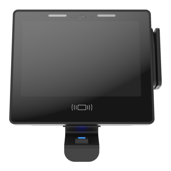
Page 7: Gt10 Features
GT10 Features This section summarises the hardware and software features of the GT10 terminal, shown below. Page 7... -
Page 8: Hardware Specification
Hardware Specification Display 10 inch full colour capacitive multi-touch display with toughened glass for use in high traffic environments 16:9 aspect ratio, 1280 x 800 pixel resolution Processor Industrial specification ARM Cortex A9 Quad Core 800MHz Operating System Android 6.0 A choice of optional input/output accessories are available, including: Contactless smartcard readers: Mifare, iClass SE Proximity card readers: supports a full range of reader types, including HID Prox 125kHz Magnetic stripe card reader... -
Page 9: Operating Temperature
Hardware Specification Operating Temperature 0°C - 45°C (32ºF to 113ºF) Plug and Play Deployment Fast easy installation Easy to fit reader modules and peripherals Integration Supports native Android and HTML 5 apps Software Developers Kit available Sound 2x Integrated speakers Integrated Microphone Camera 5 mega-pixel, wide angle;... - Page 10 Hardware Specification Front Indicators Camera and Microphone Module Power over Ethernet (PoE) Green - 12Vin power present Camera and microphone may be Module Position Blue - PoE power present - Running on battery removed by extracting the two Optional module enables terminal to screws and withdrawing the module be powered via the Ethernet cable Camera active...
-
Page 11: Opening And Fitting Front Panel To Back Panel
When separated, lift front panel to remove The GT10 Terminal can be customised by fitting a range of option modules. Internal Proximity Reader Modules For reading credentials including cards and tags HID 125KHz Reader Module... -
Page 12: Software
Software Operating System Android 6.0 Supports native Android and HTML 5 apps Remotely upgradeable/configurable Page 12... -
Page 13: Installation
(refer to Power Options for GT10) The environment the GT10 will be installed into – if the GT10 is to be installed into outdoor, wet, harsh or extreme environment then the AE-ENC-EP-GT10 environmental protection enclosure should be used to protect the GT10. -
Page 14: Power Options
The Terminal can be powered from a suitable By fitting optional module CM-POE-HC-IT the 12Vdc power supply with 2.1mm DC plug centre GT10 may be powered via the Ethernet cable with positive connected to the ‘+12V DC’ power in jack. suitable upstream PoE switch or injector. Supported... -
Page 15: Battery Backup
Power Options Battery Backup The GT10 has provision for a backup battery to run the Terminal should the normal power supply fail. To implement battery backup an optional battery pack needs to be fitted, which is accommodated within the front panel. The standard battery pack is EM-BB- 2HR-A which provides up to 2-hours runtime. -
Page 16: Installing Option Modules
Connect the reader module Fix screws in module to Tighten screws until module is ribbon cable to the GT10 threaded bushes in front firmly fixed but take care to not READER 1 connector panel with cable tucked under... -
Page 17: Fitting Card Swipe Reader Modules
Installing Option Modules Fitting Card Swipe Reader Modules Barcode Reader Module RM-BAR-A Magnetic Stripe Reader Module RM-MAG-A The fitting position for a swipe module is indicated by the box below. Swipe Reader Mounting Position Insert the tabs on the reader Screw down the two fixing Connect module by fitting module into the front panel... -
Page 18: Fitting The Battery Pack
Installing Option Modules Fitting the Battery Pack The battery pack fits into the compartment outlined below and connects to the BATTERY connector arrowed. Release the hook and loop strap Loop the strap through the eye and pull the strap then secure the hook and loop. The strap should be a loose fit around the battery to allow for some expansion. -
Page 19: Fitting The Power Over Ethernet Module
Installing Option Modules Fitting the Power Over Ethernet Module The fitting position for the PoE module is indicated by the box shown. Manoeuvre the module into position as shown Press the module down until it clicks into place on the three mounting pillars Removing the PoE Module Use a flat blade screwdriver to lever the module Reposition the screwdriver and fully release the... -
Page 20: Fitting The Wi-Fi Module
Installing Option Modules Fitting the Wi-Fi Module The fitting position for Wi-Fi module and antennae is illustrated below. Page 20... - Page 21 Installing Option Modules Fit the module as illustrated below to socket JP4 and secure with screws. Fit the two antennae to the case. These are secured with loop and hook fastening, the loop part is fitted to the front panel during manufacture in the two antenna locations.
-
Page 22: System Start-Up
System Start-up When the system is powered on, a bootloader runs which loads the Android operating system. This runs start-up scripts to set up and configure the terminal and to start enabled services. When an application is installed, once the unit is fully booted, the initial screen gives you the opportunity to enter the Terminal Setup by pressing the cog icon on the launcher start-up screen as shown below: The terminal will otherwise automatically proceed to run the installed application. -
Page 23: Terminal Shutdown
When the GT10 has the battery backup option installed the unit will continue to run following a power failure until the battery capacity reaches a low threshold where the graceful shutdown will be triggered. The unit will be powered off at the end of the process. -
Page 24: Terminal Recovery
Terminal Recovery Software Reset Android provides a mechanism for the user to remove installed packages and data from the device. This is found under "Settings->Backup & reset->Factory data reset" menu. Recovery Menu The recovery menu can be accessed by pressing and holding the button marked "RECOVERY" whilst the terminal is powering up. -
Page 25: Terminal Setup
Terminal Setup The set-up menus allow the terminal configuration to be changed at the terminal. Accessing the Terminal Setup To access the Terminal setup Settings menu allow the Terminal to boot then select ‘Admin’ . A PIN is required to enter setup mode, the default is 1905. From the Apps menu select ‘settings’ as shown below: The default PIN is 1905 The default PIN is 1905 however it is... -
Page 26: Configuring Network Settings
Terminal Setup Configuring Network Settings Wired network and Wi-Fi are configured through the Settings menu. Selecting one of these items will open a further dialogue where the settings can be entered. When selecting Wi-Fi, the wireless must be enabled to see available networks. Page 26... -
Page 27: Configuring Readers
Terminal Setup Configuring Readers The GT10 can accommodate a wide range of reader types and credential format. Setting up a reader has two elements. Reader Type – this relates to the reader hardware and its connection to the system e.g. proximity, Wiegand, magstripe etc. -
Page 28: Reader Configuration
Terminal Setup Reader Configuration Depending on the reader type the options will vary. Readers are categorised as Proximity or Swipe, with subsections within each category for individual reader types. The example below shows a selection under the Proximity Reader heading where the reader type and decoder can be chosen. Page 28... -
Page 29: Wiegand Bitmask
Terminal Setup Wiegand Bitmask In addition to the standard fixed decodes for reader data a configurable bit mask can be applied to create custom decodes. Selecting ‘Wiegand bitmask’ as the decoder type will open a dialogue for the bitmask to be entered. -
Page 30: Testing Readers
Terminal Setup Testing Readers The GT10 includes a utility to display the output of a reader to validate correct functioning and setup for readers. The utility is accessed from the ‘Readers & peripherals’ dialogue as illustrated below: Terminal Health Information The GT10 monitors key elements of the system and can display their status, accessed by selecting health from the ‘Settings’... -
Page 31: Testing The Camera
Testing the Camera Selecting the Camera icon will enable the GT10’s camera and a live picture will appear on the terminal display. There is a camera active indicator to the right of the camera which is lit when the camera is operating. -
Page 32: Software Update Service
The service also provides methods for easy provisioning and deployment via network or USB. For detailed information regarding the Software Update Service please contact Grosvenor Technology. The Software Update Service Application At the terminal the Software Update Service application can be run, this allows an administrator to: View the available updates for installed packages which have newer version(s) available in the remote repository. -
Page 33: Deployment
A memory stick formatted as FAT32 is required and prepared with the Provisioning File loaded. For details of the memory stick preparation please contact Grosvenor Technology. Start the “USB Install” utility (from the Apps screen) on the terminal and insert the memory stick in one of the free USB connectors. -
Page 34: Care And Maintenance
For a smear-free finish, polish with a dry, clean, lint-free cloth. DO NOT use any other janitorial products, acids, solvents, polishes or abrasives. As long as the care instructions for the GT10 are followed, there is no need for regular maintenance of the device (other than the battery).
Need help?
Do you have a question about the GT10 and is the answer not in the manual?
Questions and answers