Table of Contents
Advertisement
Quick Links
Advertisement
Table of Contents
Troubleshooting

Subscribe to Our Youtube Channel
Related Manuals for Luna ODiSI 6


Summary of Contents for Luna ODiSI 6
- Page 1 User’s Guide │ODiSI 6...
- Page 2 Please contact your local waste authority for instructions on proper recycling of the electronic product(s) described in this User Guide. Optical Distributed Sensor Interrogator Model ODiSI 6: User’s Guide ODiSI 6 Software © 2020 Luna Innovations Inc.
-
Page 3: Table Of Contents
View and Evaluate Sensor Status ..................16 Set Up the ODiSI for Data Logging ..................19 Run a Test ........................21 View Test Data ........................24 6 Using the ODiSI 6 Software ....................28 Operational Parameters ....................28 Instrument Status ......................28 Operational Parameters ....................28 Channel Status ......................32 Example: Operational Parameters ................35... - Page 4 Stream in ODiSI Measurement Data .................74 ODiSI Remote-control Interface ..................75 ODiSI Remote-control Commands ................75 ODiSI Controller Status .....................76 ODiSI Remote-control Workflow ................78 8 ODiSI Measurement Streaming Protocol (OMSP) ..............81 Terminology ........................81 Channel ........................81 Sensor ........................81 Gage .........................81 ODiSI 6 User’s Guide Page iii...
- Page 5 9 Additional Information ......................92 Sensing Results near the Fiber Termination ..............92 System Operation Guidelines ..................93 Vibration Tolerance ......................93 Test Setup.........................93 Strain Test Setup ......................93 Troubleshooting Dropouts ..................93 General Troubleshooting ...................95 10 Product Support Contact Information ...................98 ODiSI 6 User’s Guide Page iv...
-
Page 6: Glossary
A port on the front panel of the ODiSI instrument. There is a Channel maximum of 8 channels on an ODiSI. A set of Luna defined hardware and software parameters that change the measurement capabilities of the ODiSI instrument. Measurement parameters that change between configurations... - Page 7 Gage. Sensor (Strain) A fiber optic cable sensitive to strain. Continuous Fiber Grating (CFG) fiber sensor sold by Luna. Rather than utilizing the intrinsic Rayleigh backscattering of the Sensor (CFG) fiber, fiber Bragg gratings are written into the fiber and utilized by the ODiSI system to make distributed measurements.
-
Page 8: Safety
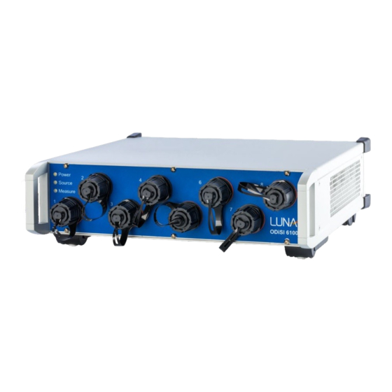
être altérées ou rendues inefficaces. 3 System Overview Luna Innovations’ Optical Distributed Sensor Interrogator (ODiSI 6) is a strain and temperature measurement system designed to meet the needs of engineers and scientists who are performing material characterization, process control, structural testing, and service life monitoring of vehicles, components, power systems, and a variety of other applications. -
Page 9: Odisi Instrument Specifications
A test with Luna CFG sensors cannot contain other sensor types. The table below outlines the performance specifications for different configurations. Further details can be found in the product data sheet, which is available on the Luna website (www.lunainc.com). - Page 10 This User’s Guide uses examples and graphics from a setup with multiple sensors. It is important to note, however, that whether the system is set up for one or multiple sensors, the hardware setup and the application interface remain consistent. ODiSI 6 User’s Guide Page 9...
-
Page 11: Hardware And Physical Setup
ODiSI 6 Hardware and Physical Setup The ODiSI 6 system is shipped with the following key components: Optical Distributed Sensor Interrogator (ODiSI 6) Dedicated Instrument Controller Standoff Cable(s) Remote Module(s) Optical Fiber Bulkhead Optical Fiber Connector Flash drive with user guides... - Page 12 Note: Repeat steps 5 and 6 for each remote module that came with the configuration. 7. Unpack and set up the instrument controller (laptop) according to the manufacturer’s instructions. 8. Connect the ODiSI 6 to the controller using the supplied USB 3.1 Gen I cable.
-
Page 13: Software Overview
Figure 4-1: Main screen of the user software This chapter provides an overview of the functionalities available in the ODiSI 6 user software. Instructions for how to quickly set up a test and log data are found in the next chapter (Software Quick Start Guide). -
Page 14: Manage The Sensor Repository
2. Automatically identify the sensor (for most Luna fiber sensor types). This reference file is also called a sensor key and is contained in Luna-labeled flash drives shipped with each sensor. In order for an ODiSI to make measurements from a sensor, that sensor’s key needs to be installed onto the controller prior to use. -
Page 15: View Test Data
Double click the “OD6” desktop shortcut. The application window will display an “Initializing” status. Once this reaches 100%, the main software interface is active. 2. Check that the “Status” is updated to “Ready”. ODiSI 6 User’s Guide Page 14... -
Page 16: Installing A Sensor
Plug the flash drive containing the sensor key into a USB port of the ODiSI controller. b. Open the menu by clicking the button in the top-left corner. c. Click on “Tools → Manager Sensors” to bring up the Manage Sensor Dialog as show in the figure. ODiSI 6 User’s Guide Page 15... -
Page 17: View And Evaluate Sensor Status
Click “Close” to exit the “Manager Sensors” window. Figure 5-3: Manager Sensors window with Install Sensor dialog View and Evaluate Sensor Status 1. Add the identified sensor to the channel configuration. Do this by clicking the button beside the identified sensor. ODiSI 6 User’s Guide Page 16... - Page 18 Figure 5-5: General Settings dialog 3. Click on the “View” button. Figure 5-6: Added identified sensor to test configuration on channel 1, View button enabled 4. Click the “Fit Plot” button to auto-scale the measurement vs. length plot. ODiSI 6 User’s Guide Page 17...
- Page 19 Apply a localized hot or cold touch to the sensor at the gage location of interest. c. A red vertical cursor will appear at the touch location. d. Click the “Add Gage” button. e. Repeat the above steps for other gages of interest. ODiSI 6 User’s Guide Page 18...
-
Page 20: Set Up The Odisi For Data Logging
Figure 5-9: Check the "Save Test" checkbox b. Click on “File → Set Test Data File Save Options” to specify the test name, notes and destination folder. Figure 5-10: Menu item for test data file saving options ODiSI 6 User’s Guide Page 19... - Page 21 Click the check box next to “Temporal Downsampling Factor” and specify the “Temporal Downsampling Factor” to down-sample from the full data rate. c. Click “OK” to save these settings and close the dialog. ODiSI 6 User’s Guide Page 20...
-
Page 22: Run A Test
1. Lock the current test configuration and prepeare the ODiSI to acquire data by clicking the “Arm” button. The Sensor Plot screen will be displayed. 2. Click the “Start” button to start logging data. You can view the measurement versus length in the “Sensor Plot” screen. ODiSI 6 User’s Guide Page 21... - Page 23 Figure 5-14: Sensor Plot screen updates with live data after clicking Start 3. View sensor single plot screen by selecting the “Single Plot” from the associated drop-down menu. Figure 5-15: Plot type selection 4. The sensor single plot screen will be displayed. ODiSI 6 User’s Guide Page 22...
- Page 24 Plot” by checking the corresponding checkboxes in the list. The color for a particular gage line can be changed by clicking the corresponding color square and selecting the desired color in the dialog that appears. ODiSI 6 User’s Guide Page 23...
-
Page 25: View Test Data
Figure 5-19: Live plot for the enabled gages over time 7. Click the “Stop” button once the test is complete. View Test Data 1. Play back test data. a. Click the “Tools → Playback Test Data” menu to display the ODiSI Player ODiSI 6 User’s Guide Page 24... - Page 26 Figure 5-21: Playing back the test data 2. Convert binary test data into ASCII format. a. Click the “Tools → Generate Test Data TSV Files” menu item to open the “Generate Test Data TSV Files Dialog”. ODiSI 6 User’s Guide Page 25...
- Page 27 Figure 5-23: Select Test Data file(s) for conversion to TSV file(s) c. Select the folder to which TSV files will be written. Then click “Save”. d. Once file conversion is complete, the status will be indicated in a pop-up window. ODiSI 6 User’s Guide Page 26...
- Page 28 ODiSI 6 Figure 5-24: Completion status for generating TSV file(s) ODiSI 6 User’s Guide Page 27...
-
Page 29: Using The Odisi 6 Software
ODiSI 6 6 Using the ODiSI 6 Software This section describes in detail all the functionality of the ODiSI 6 Software. Operational Parameters When first launched, the user interface displays the system Status and Sensor Properties. Among other things, the “Sensor Properties” screen displays the current state of the system including information on the configuration of each channel and detailed information for each sensor. - Page 30 Luna CFG Sensing Select “Settings → General” as described above and select the “Luna CFG Sensing” option from the “Measurement Mode” drop-down. Note that the Gage Pitch selected is 6 mm and it cannot be changed. Upon clicking “Ok”, the CFG Sensor Properties Screen is displayed.
- Page 31 ODiSI 6 Figure 6-2: Sensor Properties screen when using Luna CFG Sensing The user must manually select the sensor that is connected to a given channel on the ODiSI. It is recommended to name the installed CFG sensors so that they are more recognizable to the user.
- Page 32 ODiSI 6 Figure 6-3: Luna CFG sensor is ready All other operations such as viewing the sensor, defining gages and segments, and running a test are the same as other sensor types. Note that when viewing a sensor plot, the 0-meter x- axis position for these CFG sensors corresponds to the first grating for which results are returned;...
-
Page 33: Channel Status
Status: Indicates the status of each channel. Below are various text strings that could be listed for each channel, with multiples possible, separated by dashes: • “Identifying...” • “Remote module type does not match Measurement Mode setting” • “No remote module connected” • “No sensor connected” • “Identified” ODiSI 6 User’s Guide Page 32... - Page 34 The Key being used for the identified sensor (if a sensor has been rekeyed). • The Tare being used for the identified sensor. • The type of Remote Module being used on that channel, either Standard or Extended. ODiSI 6 User’s Guide Page 33...
- Page 35 (--), Standard, or Extended. Sensor Info: Indicates what sensor has been identified on each channel. Click on the button to add the identified sensor to the configuration of the specific channel. ODiSI 6 User’s Guide Page 34...
-
Page 36: Example: Operational Parameters
Status of Channel 2 in black. • Channel 3: A 5.24 m strain sensor has been identified as being connected to the remote module through a 3.18 m patch cord. This does not match the original ODiSI 6 User’s Guide Page 35... -
Page 37: Manage Sensors
Delete Deactivated Sensor: Click the to delete a deactivated sensor. Note: This will permanently remove the sensor and any associated data from the system’s memory, including Tares, Rekeys, and Gages and Segments. ODiSI 6 User’s Guide Page 36... -
Page 38: View And Evaluate Sensor Status
Rekey: Select the specific Rekey to use with the listed sensor. Install Sensor: Click to install a sensor from a Luna-provided flash drive containing the sensor key. Install sensor will also install a package file that was exported via Export Sensor. The package file contains Tares, Rekeys, and Gages and Segments associated with this sensor.. -
Page 39: Sensor Tare
Rekey: Click this button to capture a new Rayleigh backscatter reference for this sensor. Key dropdown menu: Select from multiple sensor keys to be used for the sensor. Delete Key: Click to delete the selected Rekeyed trace. ODiSI 6 User’s Guide Page 38... -
Page 40: Define Gages
Start Gage to the default End Gage. Table of Segments Segments are continuous sections of measurement data that start and end at previously defined gages. To create a Segment, choose the start and end Gages from the dropdown ODiSI 6 User’s Guide Page 39... -
Page 41: Plot Navigation
Figure 6-10: Gages and Segments Plot Navigation The ODiSI 6 software uses plots and graphs to display measurement data. The X and Y axes of these plots can be rescaled to better view features in the measurement data. Unconstrained Zoom In/Out To zoom in on data in both X and Y, move the mouse cursor to the region of interest and use the scroll wheel to zoom in or out. -
Page 42: Set Up The Odisi For Data Logging
Directory: Click “Browse” to change the Test Data logging directory. Figure 6-13: Specify test data tile saving options Test data files are saved to the local drive under the OD6_Test Data Directory. Clicking the “Browse” button will display the Test Data File Dialog. ODiSI 6 User’s Guide Page 41... - Page 43 To save a file to an external drive, click the external drive button which will navigate to an external drive connected to the controller through USB. Figure 6-15: Navigate to an external drive to save test data ODiSI 6 User’s Guide Page 42...
-
Page 44: Managing Test Data Files
Figure 6-17: Select files and/or directories to move 3. To delete test data files or directories, select one or more test data files and/or directories and click the delete button. ODiSI 6 User’s Guide Page 43... -
Page 45: Copy Test Data
Select the files and/or directories to copy on the right file browser. d. Click the “Receive” button. Figure 6-19: Copy test data to USB/CDROM 2. To copy files from a USB/CDROM drive: a. Select the drive type on the left file browser. ODiSI 6 User’s Guide Page 44... -
Page 46: Copying Test Data Tsv Files
Select the drive type on the left file browser. b. If using a USB drive, select the desired directory on the left file browser. c. Select the files and/or directories to copy on the right file browser. ODiSI 6 User’s Guide Page 45... - Page 47 Select the drive type on the left file browser. b. Select the files and/or directories on the left file browser c. Navigate to the directory on right file browser d. Click the “Send” button. ODiSI 6 User’s Guide Page 46...
-
Page 48: Settings Menu
Measurement Mode: Select the Measurement Mode that matches the sensor lengths and remote modules connected to each channel. Gage Pitch: The gage pitch selection specifies the distance between the center of one gage and its nearest neighbor. ODiSI 6 User’s Guide Page 47... - Page 49 Standoff Length: Select standoff cable length per channel from the drop-down menus (10 m, 50 m, 100 m, 150 m, or 200 m). The longer lengths can be achieved by connecting two shorter standoff cables together using a Luna provided connector. ODiSI 6 User’s Guide...
- Page 50 ODiSI Measurement Streaming Protocol (OMSP). Luna also provides the ODiSI Remote application which gives the ability to Arm, Start, Stop, and Disarm the ODiSI controller software from a remote PC as well as receive and display live measurements from the ODiSI control software in real-time. The ODiSI Remote software is covered in more detail in a later section.
- Page 51 Streamed measurements are sent to a third-party PC and no record of them is maintained by the instrument controller. You can enable and utilize both of these features simultaneously. Figure 6-29: Streaming Properties dialog ODiSI 6 User’s Guide Page 50...
- Page 52 ODiSI instrument is actively acquiring measurement data. Start: Time Interval Select the time interval between subsequent automatic Starts. Stop: Measurement Count This is the number of scans taken each time a start trigger signal is received. ODiSI 6 User’s Guide Page 51...
- Page 53 Select the Strain Settings menu by clicking “Settings → Strain”. Figure 6-32: Strain settings menu item Y-Axis Units: Displays the Y-Axis Units for Strain. Figure 6-33: Strain settings dialog Temperature Sensor Select the Temperature Settings menu by clicking “Settings → Temperature”. ODiSI 6 User’s Guide Page 52...
- Page 54 Temperature Offset: When used together with a Tare for the temperature sensor, the temperature offset effectively converts the temperature change measurements into absolute temperature. Figure 6-35: Temperature settings dialog Filter and Downsample Select the Filter and Downsample Settings menu by clicking “Settings → Filter and Downsample”. ODiSI 6 User’s Guide Page 53...
- Page 55 Measurement Rate Per Channel: Measurement rate that will be achieved on each channel. This rate depends on the sensor length, Measurement Mode, Gage Pitch, Performance Mode, number of channels, and Temporal Downsampling Factor. Figure 6-37: Filter and Downsample settings dialog ODiSI 6 User’s Guide Page 54...
- Page 56 Gage: Select the gage associated with the selected sensor. During a test run, the strain/temperature value of the selected gage will be scaled to the appropriate output value and driven out on the associated DAC channel. ODiSI 6 User’s Guide Page 55...
-
Page 57: Run A Test
The Sensor Plot screen displays measurements along sensor length once a test has Started. The screen displays data for the sensors that are included in the active configuration as shown in the Sensor Properties screen. Sensors that are no longer part of the current test ODiSI 6 User’s Guide Page 56... -
Page 58: Gage Plot
Check the associated checkbox for a given Gage to have the line graph for that Gage appear on the Gage Plot. Click the color square to customize the color associated with a Gage. The color selection will be saved and remain the same for subsequent tests. ODiSI 6 User’s Guide Page 57... -
Page 59: View Test Data
Play Back mode. Browse for a test data file from the menu bar using “Tools → Play Back Test Data”. Navigate to the test file and click Open. ODiSI 6 User’s Guide Page 58... - Page 60 Clicking the right arrow will display the associated clip files which can be read into the player. The icon denotes a clip file. Figure 6-43: Example list of test data files ODiSI 6 User’s Guide Page 59...
- Page 61 Backward and forward buttons: Step through the test file one measurement at a time. Slider: Drag the blue slider across the top of the Sensor Plot to scroll through the data. ODiSI 6 User’s Guide Page 60...
- Page 62 Remove Clip: Click to remove clip and play back original full input file. Save Clip: Save clip file by clicking “File → Save Clip” ODiSI 6 User’s Guide Page 61...
-
Page 63: Generate Tsv File
The test data collected during a test is stored in a non-human readable binary format. This data can be exported to an easily readable, tab separated, text file for further analysis. Select test data files for conversion from the menu bar using “Tools → Generate Test Data TSV Files”. ODiSI 6 User’s Guide Page 62... - Page 64 Select Channel(s): Select subset of Channels for which a TSV file is to be generated. Index Range: Specify the scan index range to be written to the TSV File to limit the amount of data. Select the directory to which TSV files are stored. ODiSI 6 User’s Guide Page 63...
- Page 65 The Gages and Segments converted TSV file contains 1 more header row compared to the Full converted TSV file, where the Gage Names are included above each Gage Location. A snippet of a test data TSV file is shown below. ODiSI 6 User’s Guide Page 64...
- Page 66 ODiSI 6 Figure 6-53: Example test data TSV file ODiSI 6 User’s Guide Page 65...
-
Page 67: Manage Configuration
Figure 6-55: Load previously saved configuration The loaded configuration is displayed on the top right of the User Interface. Figure 6-56: Configuration name is displayed when configuration is loaded ODiSI 6 User’s Guide Page 66... - Page 68 Figure 6-58: Set default configuration To remove the default configuration, click the “No Default” button. Delete Configuration: Click “Configuration → Delete Configuration” to delete the current saved configuration from the system. Figure 6-59: Delete the current saved configuration ODiSI 6 User’s Guide Page 67...
-
Page 69: Update Feature Keys
Click “Tools → Update Feature Keys” to update the software with optionally purchased features. Once the file dialog is displayed, select the Luna provided feature key update file. The ODiSI software must be restarted after updating the feature keys on the instrument. -
Page 70: Help
• User Guide: Matching version of the ODiSI 6 User’s Guide. • Setup Guide: Instructions for how to set up the ODiSI 6. • Sensor Application Guide: Comprehensive guide containing the best methods for attaching a fiber optic strain sensor to a test article. -
Page 71: Send Us Feedback
Figure 6-64: Send Us Feedback menu item Generate a report on any issues encountered while running the ODiSI software or feature requests associated with software functionality. This report is packaged for subsequent emailing to Luna support. ODiSI 6 User’s Guide Page 70... -
Page 72: Update
ODiSI 6 Figure 6-65: Form for providing feedback to Luna Update Figure 6-66: Software update menu item Update the ODiSI software to the latest version, or downgrade to a previous version. The ODiSI software will automatically restart once the update is initiated. -
Page 73: Language
Language Select the language to be used in the ODiSI software user interface. The ODiSI software must be restarted for the language selection to be applied. Figure 6-68: Menu to select user interface language ODiSI 6 User’s Guide Page 72... -
Page 74: About
ODiSI 6 About Figure 6-69: About info menu item Displays the ODiSI software version information, connected hardware information, list of optional installed features and Luna contact information. Figure 6-70: About info dialog ODiSI 6 User’s Guide Page 73... -
Page 75: Odisi Remote Operation
Measurement data as defined by Gages and Segments will be streamed into the ODiSI Remote application and can be displayed on a Sensor Plot. Within the Sensor Plot, Gages will be displayed as circle markers while Segments will be displayed as a line plot. ODiSI 6 User’s Guide Page 74... -
Page 76: Odisi Remote-Control Interface
ODiSI Remote-control Commands The following table describes the remote-control commands that can be sent after establishing a connection. Table 7-1 List of remote-control commands Command Description remote:arm Arm Test remote:disarm Disarm Test remote:start Start Test ODiSI 6 User’s Guide Page 75... -
Page 77: Odisi Controller Status
Intrument is armed status:arming Intrument is arming status:start Instrument started test status:noinstrument No instrument is connected to the controller status:notready Controller is in a state where it is not ready. (Example: Incorrect configuration, no sensors connected) ODiSI 6 User’s Guide Page 76... - Page 78 TEXT) is a single line of comma separated values (CSV) where each value in the CSV set is the sensor name for the corresponding channel on the ODiSI (or sensor serial number if the sensor does not have a user- ODiSI 6 User’s Guide Page 77...
-
Page 79: Odisi Remote-Control Workflow
Controller is connected to an Instrument and is Ready status:identified_sensors=TEXT Controller sends list of identified sensors Remote turns on saving remote:set_filesave_on test data file status:filesave_on Controller sets file saving ODiSI 6 User’s Guide Page 78... - Page 80 Remote remove channel remote:remove_channel=# status:remove_channel_success=# Remove channel succeeded status:remove_channel_failure=# Remove channel failed Remote arms instrument remote:arm status:arming Instrument Arming status:armed Instrument Armed Remote starts test remote:start status:start Instrument started test Remote stops test remote:stop ODiSI 6 User’s Guide Page 79...
- Page 81 Remote requests remote:getfile download of latest test file. status:filesend_start Controller initiates test data file download to the remote. Controller sends content of file to the Remote. status:filesend_done Controller completes the file download to the remote ODiSI 6 User’s Guide Page 80...
-
Page 82: Odisi Measurement Streaming Protocol (Omsp)
The ODiSI measures strain or temperature at multiple points along a sensor. Channel The ODiSI acquires data from multiple channels (1 to 8 for the ODiSI 6). A different strain or temperature sensor is attached to each channel. The channel number is used in OMSP to specify which sensor is being referred to. -
Page 83: Segment Vector
(if they appear in the user data). A quote mark is represented as \” in the JSON string. A backslash is represented as \\. These are the only characters that need to be escaped ODiSI 6 User’s Guide Page 82... -
Page 84: Metadata Messages
“system status” String. “stopped” or System status “measuring”. “sensors” Array of sensors Array of JSON elements contained in [] brackets “measurement rate” Measurement rate per Decimal number indicating channel measurement rate per channel. ODiSI 6 User’s Guide Page 83... - Page 85 Table 8-2 OMSP Sensor Information. Description JSON name Value “channel” Channel Integer. 1-8 for ODiSI 6. “sensor name” Sensor name String. User defined in ODiSI software. “sensor serial number” Sensor serial number String “sensor part number”...
- Page 86 The JSON portion of the Metadata Message is followed by a 16 bit CRC-16-ANSI (0x8005) checksum, encoded as a 4-character hexadecimal number. The checksum is calculated over the entire length of the JSON text, beginning with the starting curly ODiSI 6 User’s Guide Page 85...
-
Page 87: Example
"location (mm)": 2517 }, { "gage name": "Right back", "location (mm)": 4487 }, "segments": [ { "segment name": "Segment B", "location (mm)": 1543, "size": 65 }, { "segment name": "Segment C", "location (mm)": 3307, "size": 40 } ODiSI 6 User’s Guide Page 86... -
Page 88: Measurement Message
The JSON value null will be used to indicate a NaN, or “not a number” value. (Under certain conditions, the ODiSI may not be able to calculate a strain or temperature value for a certain gage. In these events, the ODiSI reports NaN as the gage value). ODiSI 6 User’s Guide Page 87... - Page 89 String. Ex: “UTC-0” Time zone “channel” Channel Integer. Should match one of the “channel” fields in the “sensors” array Metadata Message. 1 - 8 for the ODiSI 6. “number of gages” Number of gages Integer ODiSI 6 User’s Guide Page 88...
-
Page 90: Example
(\r\n) follows the closing curly brace of the JSON text. A CRC- 16-ANSI (0x8005) checksum (encoded as 4 hexadecimal characters) follows the carriage return plus line feed. A NULL character follows the checksum and marks the end of the message. ODiSI 6 User’s Guide Page 89... - Page 91 String “channel” Channel Integer. Should match one of the “channel” fields in the “sensors” array of the Metadata Message. 1 - 8 for ODiSI 6. “number of gages” Number of gages Integer “data” Data Array of decimal numbers. The JSON value null indicates NaN.
-
Page 92: Example
TCP packets in order to assemble a message whose end has not been received, the program should discard the previous partially-received message and begin processing a new message starting with the new packet. ODiSI 6 User’s Guide Page 91... -
Page 93: Additional Information
How much space does the ODiSI 6000 put between where it locates the sensor termination and the end of strain or temperature sensing? Consider the illustration of the termination end of a Luna fiber sensor: Figure 9-1: Illustration of the termination end of a Luna fiber sensor 1. -
Page 94: System Operation Guidelines
Help menu on the ODiSI 6. Troubleshooting Dropouts The ODiSI 6 relies on a correlation of reference and measurement gage data to calculate the strain along the sensing fiber. Environmental disturbances such as mechanical vibration can lead to a degradation of the measurement data. - Page 95 ODiSI 6 calculation. the amount of strain variation across a given gage length. ODiSI 6 User’s Guide Page 94...
-
Page 96: General Troubleshooting
Solution(s) The ODiSI 6 and the controller require separate power The ODiSI 6 and/or the cords. Plug in the ODiSI 6 and/or the controller, or replace controller is not plugged dead batteries with charged ones. Instructions for the in or turned on (and the... - Page 97 Cracks in bulkhead Contact Luna Technologies at 1-866- LUNAOVA or connector alignment solutions@lunainc.com for service. sleeve No Data After Measurement...
- Page 98 Restart the controller and the control software. software The USB cable is faulty Replace the cable Turn computer off. Communication Error Turn on ODiSI 6. Restart Computer. Power cycle the instrument and controller. Relaunch the Laser error software ODiSI 6 User’s Guide...
-
Page 99: 10 Product Support Contact Information
ODiSI 6 10 Product Support Contact Information Contact Luna’s technical support staff with concerns or questions using one of the following methods. Headquarters: 3155 State Street Blacksburg, VA 24060 Main Phone: 1.540.961.5190 Toll-Free Support: 1.866.586.2682 Fax: 1.540.961.5191 Email: solutions@lunainc.com Website: www.lunainc.com...
Need help?
Do you have a question about the ODiSI 6 and is the answer not in the manual?
Questions and answers