
Subscribe to Our Youtube Channel
Related Manuals for Luna Acuity LS


Summary of Contents for Luna Acuity LS
- Page 1 Acuity LS PERATING ANUAL CUITY ORROSION ANAGEMENT OLUTIONS #OMA20200327 sensinst@lunainc.com...
-
Page 2: Table Of Contents
Battery Replacement ..........................6 System Restart ............................7 4 . Software and Driver Installation ....................... 7 Acuity LS User Interface Software and USB Driver Installation ............... 7 5 . Software Operation ..........................8 Establishing Communication ........................8 Operating the User Interface ........................10 Clock Synchronization .......................... -
Page 3: Overview
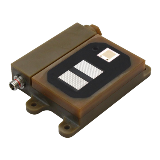
The commercially available battery can be replaced by the user. Acuity LS Interface software enables users to configure each Acuity LS device at startup and collect data. Acuity LS corrosion sensing elements are replaceable by the user. Replacement Acuity LS Lid Sensor Panels (LSP) may be purchased from Luna. -
Page 4: Hardware Setup
The Acuity LS device is delivered fully assembled with LSP installed on base. The following instructions are only needed for replacement of an LSP. The replacement LSP is delivered with a new O-ring seal installed. For set up of new Acuity LS device please skip to next section "LSP Surface Preparation for Testing". -
Page 5: Lsp Surface Preparation For Testing
(isopropyl alcohol) using a non-abrasive foam or cotton swab can be done. CAUTION: Do not immerse the Acuity LS device or flood the filter cap area that houses the relative humidity and temperature sensor with solvent, this could affect the temporary operation of these sensors or cause permanent damage. -
Page 6: Battery Replacement
The Acuity LS device and LSP can be used with coatings. Please contact Luna for specific instructions for coating the LSP and using the Acuity LS device to measure coating performance. -
Page 7: System Restart
System Restart To perform a system restart of the Acuity LS device, remove the battery and wait 10 seconds, then install the battery per the instructions above. Performing a system restart has no effect on the data; all data will remain stored on the Acuity LS device. -
Page 8: Software Operation
(no tools). 2. In the Windows start menu, locate the Acuity LS Interface folder and select the program (Figure Figure 5. Starting the Acuity LS Interface program. - Page 9 (Figure 7). i. For item 4 in Figure 7 please refer to "System Restart" in Section 3. ii. If there is no connection after following all the instructions, please contact Luna for support. Figure 7. COM port error message.
-
Page 10: Operating The User Interface
Sampling Interval – Displays the sampling interval in minutes currently set for the device. • Acuity LS Device ID – Displays the serial number of the connected Acuity LS device. This number should match the label on the outside of the device. -
Page 11: Clock Synchronization
The user is prompted to synchronize the Acuity LS device time with the computer time whenever starting a data log or downloading data (Figure 9). Use the Acuity LS interface program to synchronize the Acuity LS device clock with the connected computer clock. -
Page 12: Starting Data Logging
The Aircraft/Asset window can be used to enter specific information and notes about the aircraft, asset, or structure being monitored. • The Acuity LS device window can be used to enter specific LSP or other information about the materials and condition of the LSP, such as coating information if used. •... -
Page 13: Download Data Log
Figure 11. Installation Description window. CAUTION: DO NOT use any “,” or carriage return (enter key) characters in the provided Notes text boxes. 6. Select "START DATA LOGGING" to begin Acuity LS device data collection and storage. A dialog box will appear indicating that the Acuity LS device data logging has started (Figure 12). -
Page 14: Suspending Operation (Pause Data Logging)
Time-integral of galvanic corrosion current to obtain total Tot Galv Corr (C) charge passed. Units of coulombs. Time-integral of free corrosion current to obtain total charge Tot Free Corr (C) passed. Units of coulombs. Acuity LS Page 14 Operating Manual #OMA20200327... -
Page 15: Unix Timestamp Conversion
NOTE: The total time-integral data in columns J – M are calculated using all stored data on the Acuity LS device. If new total time-integral data starting at zero is desired, all data must be deleted from the Acuity LS device using "Delete Data Log" in the user interface main screen (see Section 5, Figure 8). - Page 16 S Conductance (High Freq) 10,000 20 mV , 25 kHz A Free Corrosion 0.005 20 mV , 0.5 Hz A Galvanic Corrosion 0.01 Dimensions Figure 13. Acuity LS device dimensions, units in inches. Acuity LS Page 16 Operating Manual #OMA20200327...
-
Page 17: List Of Acronyms
I S T O F C R O N Y M S Acuity LS Acuity LS Corrosion Management System Compact Disk Communications FTDI Future Technology Devices International Identification Interdigitated Electrode Isopropyl Alcohol Acuity LS Lid Sensor Panel Personal Computer Relative Humidity...
Need help?
Do you have a question about the Acuity LS and is the answer not in the manual?
Questions and answers