Table of Contents
Advertisement
Quick Links
Advertisement
Table of Contents

Subscribe to Our Youtube Channel
Related Manuals for Luna 6415


Summary of Contents for Luna 6415
- Page 1 Setup Guide │Luna 6415...
- Page 2 Please contact your local waste authority for instructions on proper recycling of the electronic product(s) described in this User Guide. Luna 6415: Luna 6415 Setup Guide © 2019 Luna Innovations Inc. 3155 State Street Blacksburg, VA 24060...
-
Page 3: Table Of Contents
E-mail ..........................4 3 System Overview ........................5 Luna 6415 Hardware Configuration .................. 5 4 What you get with the Luna 6415 .................... 5 A Closer Look at the Luna 6415 ..................7 Front Panel ........................ 7 Rear Panel ......................... 8 Air Vents ........................ -
Page 4: Safety
L'utilisation de commandes, d'ajustements, de performances ou de procédures autres que celles spécifiées ici peut entraîner une exposition dangereuse au rayonnement laser et une ou plusieurs protections de sécurité peuvent être altérées ou rendues inefficaces. Luna 6415 Setup Guide Page 3... -
Page 5: Technical Support
Mail Luna Innovations Inc. 3155 State Street Blacksburg, VA 24060 Phone Main Phone: (540) 961-5190 Toll-Free Support: 1.866.LUNA OVA (866.586.2682) E-mail solutions@lunainc.com www.lunainc.com Luna 6415 Setup Guide Page 4... -
Page 6: System Overview
Luna 6415 3 System Overview The Luna 6415 provides users with the ability to make high resolution insertion loss and return loss measurements of optical devices in both reflection and transmission. These measurements can be viewed in both the delay and spectral domains for improved visibility in characterizing and screening optical components and networks. - Page 7 Optical fiber bulkhead cleaners Dedicated instrument controller Power adapter Two meter USB 3.1 Gen I cable If any components are missing or damaged, contact Luna toll free at 866-586-2682 or by e-mail at solutions@lunainc.com Luna 6415 Setup Guide Page 6...
-
Page 8: A Closer Look At The Luna 6415
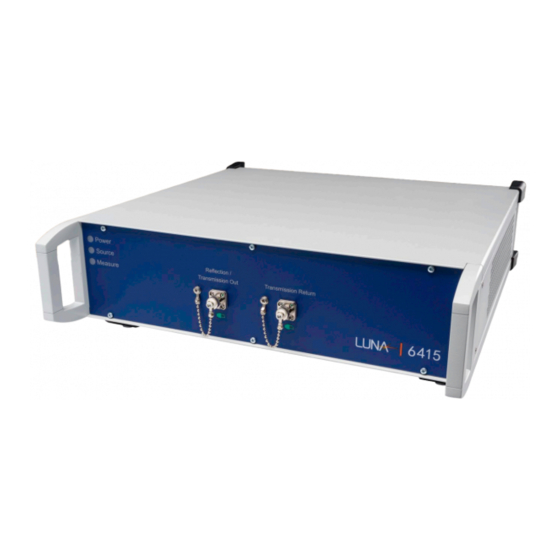
Luna 6415 A Closer Look at the Luna 6415 Front Panel The front panel of the Luna 6415 contains the two optical connectors, as well as three LED system status indicators. • Power Lit while the system is powered on •... -
Page 9: Rear Panel
Figure 4-2 – Luna 6415 Panel Air Vents Air vents are located on both the sides and rear of the Luna 6415. These vents should remain unobstructed whenever the system is powered on. Figure 4-3 - Luna 6415 Air Vents... -
Page 10: Hardware Setup
Luna 6415 5 Hardware Setup 1. Remove all of the Luna 6415 components from the packaging and verify that no components are damaged or missing (see components list). 2. For best performance, place the unit on a stable surface capable of supporting the entire weight of the unit. -
Page 11: Software Setup
Luna 6415 6 Software Setup This section provides a short introduction to the main displays in the Luna 6415 software. For complete instructions on how to start and configure the application, refer to the Luna 6415 which can be accessed from the Help menu on the Luna 6415 software. - Page 12 Figure 6-2 Spectral amplitude response plot showing the spectral amplitude of a single FBG Figure 6-3 Event tab showing found events and their associated insertion and return losses Note: It is important to disconnect any devices from the transmission port on the Luna 6415 when using the reflection measurement mode.
-
Page 13: Transmission Mode
Luna 6415 Transmission Mode The 6415 can be swapped to transmission mode using the dropdown menu located in the upper left corner of the screen. The system will configure itself for transmission measurements and then you will be able to use the same three plot types to interpret the transmission data. -
Page 14: Maintenance And Cleaning
7 Maintenance and Cleaning Optical Connector Cleaning Materials It is extremely important to clean connectors before attaching optical fibers to the Luna 6415 for testing. Failure to do so may result in noisy data or damaged equipment. Optical fiber connectors on cables should be cleaned before every connection to the Luna 6415. The bulkhead connectors on the front panel should be cleaned frequently, roughly once every 25 connections. -
Page 15: Cleaning Optical Connectors
Luna 6415 Figure 7-2 – Cletop 2.5mm Sticks Cleaning Optical Connectors 1. Expose the cleaning tape by pushing down the cover release lever. Figure 7-3 - Exposing the Cleaning Tape Luna 6415 Setup Guide Page 14... -
Page 16: Cleaning Optical Bulkhead Connections
1. Turn off the Luna 6415. 2. Make sure that no devices are connected to the Luna 6415. 3. Open the protective cover on the front panel. 4. Gently insert one of the supplied cleaning sticks, as shown below. -
Page 17: Cleaning The Air Filter
4. Remove the air filter and clean with running water. Allow the filter to dry before reassembly. 5. Insert the air filter back into the space between the top and bottom panels. 6. Replace the side panel and secure using four screws. Luna 6415 Setup Guide Page 16... -
Page 18: Cleaning The Case
2. Place the blade of a screwdriver or similar tool in the slot at the bottom of the fuse drawer, then gently pry the drawer out of the power module. Figure 7-8 - Remove Fuse Drawer Luna 6415 Setup Guide Page 17... - Page 19 3. Replace fuses with Bussmann AGC-2 type 2A @ 250VAC 1 ¼” x ¼” fast acting (FA) fuses, rated FS01008. Figure 7-9 - Insert New Fuses 4. Push the drawer back into the power module until it snaps into place. 5. Reconnect the power cord. Luna 6415 Setup Guide Page 18...
Need help?
Do you have a question about the 6415 and is the answer not in the manual?
Questions and answers