
Related Manuals for Kingfisher DIMENSION AutoGet WiFi


Summary of Contents for Kingfisher DIMENSION AutoGet WiFi
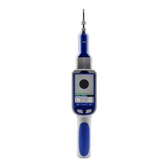
- Page 1 AutoGet WiFi Inspection Probe User Manual Dimension by Kingfisher Revision 2 Date: 15 Sep 2022 Page - 1 - of-20...
-
Page 2: Table Of Contents
Table of Content 1. Introduction ................................- 3 - 2. Features ................................. - 3 - 3. Specifications ................................ - 3 - 4. Standard Accessories ............................- 4 - 5. Optional Interchangeable Inspection Adaptors .................... - 4 - 6. Instrument layout ..............................- 5 - 7. -
Page 3: Introduction
1. Introduction The AutoGet WiFi is manufactured by our partner, Dimension. It is a fully automated tool to check and analyse fiber optic connector end faces for dirt, condition, and quality as per IEC61300-3-35 requirements. Images are auto cantered/focused and can be viewed directly on an integrated LCD display. Pass/fail analysis starts and, with its data &... -
Page 4: Standard Accessories
4. Standard Accessories Description Quantity Inspection adaptors: 1.25mm Male, 2.5mm Male, FC Female, SC Female, LC Female 1 each Adaptor storage box Captive protective cap USB charger with Interchangeable International Plug Style Adaptors (US, UK, EU, AU) 1 set USB WiFi module Snap-on Li-ion battery USB Cable (type A-type C) Touch pen... -
Page 5: Instrument Layout
6. Instrument layout Status indication LED On/off button Connector Adaptor Torch LED switch Torch LED Torch LED Battery release latch Fig. 1 Release button for adjustment of the instrument’s style/form. Touch pen Rubber flap covering SD card slot Handle Start analysis switch Fig. -
Page 6: Instrument Operation
Auto screen brightness control sensor Snap-On battery on instrument: LCD touch screen Focus buttons Battery status USB-C for charging indication LEDS & PC connection Snap-On Battery Fig. 3 7. Instrument Operation 7.1 Getting started 7.1.1 WiFi module installation The USB WiFi module usually comes with the instrument uninstalled. Remove protective label on instrument’s slots, remove cover of USB module and push the unit into instrument’s slot as shown below. -
Page 7: Sd Card Installation
7.1.2 SD card installation The instrument usually comes with a SD card already installed. To remove the card, open the rubber flap covering the SD card slot (see Fig.2 of section 6 above) on instrument and gently push the card in to unlatch it. -
Page 8: On/Off Instrument
7.1.5 On/off instrument Press and hold on/off button of instrument until the blue Status LED lights up (see Fig. 1 of section 6 above). Wait approx. 20 seconds for the instrument to boot up after which the Home Display will be shown on LCD, see picture in section 7.1.8 below. - Page 9 About submenu: Tap to do Firmware update (see section 7.5 for detail instruction). Tap to restore settings to factory defaults. Device submenu: Tap this, highlight date / month Tap and move left/right along / year / time, and use up/down the bar to adjust brightness of arrows to select the desired image.
- Page 10 Measure submenu: This submenu allows user to create customed pass/fail specifications if needed. To create a customed pass/fail To delete a created custom standard: specification by modifying a prestored IEC standard: ① Select the custom standard to be deleted from the dropdown list of ➀...
-
Page 11: Connector Adaptor Installations
7.1.9 Connector adaptor Installations For standard adaptors (non MPO): Note: It is recommended that the ① Align grove on adaptor with pin on instrument. barrel of adaptor is cleaned using cleaning sticks before installing the adaptor onto instrument. Standard adaptor The cleaning should then repeated frequently... -
Page 12: End-Face Inspection Operation
7.2 End-face inspection operation Do the following to inspect end-face of a connector without pass/fail analysis. ① Install a suitable adaptor depending on the connector type to be inspected (see section x). ➁ Switch on instrument (see section 7.1.5). ➂ Mount adaptor of instrument onto connector to be inspected. The end-face image of the connector being inspected will be displayed on the instrument as shown in the example below. - Page 13 End-face image of connector. • Tap to select “AF On” to turn • Depending on the connector on autofocusing. type to be inspected/analyzed, select the appropriate IEC specification from the drop dropdown list. • Tap on field and enter value/text via the virtue Note: keyboard.
- Page 14 For MPO12 connector: Note that this process involves a 3-step image acquisition cycle (capturing images for 4 fibers in each step) before the actual analysis. ① Install a MPO adaptor (OPT636) on instrument (see section 7.1.9). ➁ Switch on instrument (see section 7.1.5). ➂...
- Page 15 Do the 3-step image acquisitions as shown below and analysis will start automatically when all images are successfully acquired. Step-1 of image acquisition: this display, click instrument’s Start Analysis Button (see Fig. 2 of section 6) Turn knob on adaptor position “1”...
-
Page 16: Download Data From Instrument
Upon sucessful completion of all image acquisitions, analysis will begin and the results will be displayed automatically. Tap on the left-most bar (as shown below by the red arrow) to view analysis for fibers 1,2,3,4. Tap on the middle bar for fibers 5,6,7,8. Tap on the right-most bar for fibers 9,10,11,12. Overall analysis result is shown here as PASS or FAIL. -
Page 17: Instrument Firmware Update
Alternatively, the data saved in SD card can be transferred to a PC using the software, see section 8.4. Below are examples of the types of Image/data/report files saved (depending on the selected Save Option, see section 7.2). Excel Report file (the file is/are named with value/text entered on “ID” field): Excel Data file (the file is/are named with value/text entered on “ID”... -
Page 18: Software Operation
8.1 Install the software on a PC See section 3 for software compatibility. Download from Kingfisher website (kingfisherfiber.com) or from the supplied CD the installation file, “Autoget wifi x.x.x.rar” onto your PC. Upon unzipping the downloaded file, select application file “AutoGetWiFiVx.x.x”... -
Page 19: Use Software To Download Data From Instrument
8.4 Use software to download data from instrument ① Click on “FTP” access memory content instrument’s SD card. ➁ Select folder, “sd” then “Measure_Result” access analysis image/data/report files. ➂ Copy the desired from these directories onto your PC. 8.5 Software Setting Click on “Setting”... -
Page 20: Eye Safety Precaution
This manual is given in good faith for the benefit of the user. It cannot be used as the basis for claims against Kingfisher International or its representatives. This product is guaranteed against defective components and workmanship for 1 years from delivery, unless stated in the purchase contract. This warranty excludes connector adaptors or incorrect use.
Need help?
Do you have a question about the DIMENSION AutoGet WiFi and is the answer not in the manual?
Questions and answers