Table of Contents
Advertisement
Quick Links
Preface
The PIC-BLE Development Board is a small and easily expandable demonstration and development platform for
®
Bluetooth
Low Energy (BLE) solutions based on the PIC
that the design of a typical BLE application can be simplified by partitioning the task into three blocks:
•
Smart – represented by the PIC16LF18456 microcontroller
•
Secure – represented by the ATECC608A secure element
•
Connected – represented by the RN4870 BLE module
Also, the PIC-BLE Development Board features the following elements:
•
The on-board debugger (PKoB nano) supplies full programming and debugging support through Microchip
®
MPLAB
X IDE. It also provides access to a serial port interface (serial to USB bridge) and one logic analyzer
channel (debug GPIO).
™
•
A mikroBUS
socket enables the ability to expand the board capabilities with the selection from 450+ sensors
and actuators options offered by MikroElektronika (www.mikroe.com) via a growing portfolio of Click board
©
2020 Microchip Technology Inc.
PIC-BLE Hardware User Guide
®
microcontroller architecture. It is designed to demonstrate
User Guide
PIC-BLE
™
.
DS50002963B-page 1
Advertisement
Table of Contents

Subscribe to Our Youtube Channel
Related Manuals for Microchip Technology PIC-BLE


Summary of Contents for Microchip Technology PIC-BLE
-
Page 1: Preface
PIC-BLE PIC-BLE Hardware User Guide Preface The PIC-BLE Development Board is a small and easily expandable demonstration and development platform for ® ® Bluetooth Low Energy (BLE) solutions based on the PIC microcontroller architecture. It is designed to demonstrate that the design of a typical BLE application can be simplified by partitioning the task into three blocks: •... -
Page 2: Table Of Contents
Assembly Drawing........................27 The Microchip Website..........................28 Product Change Notification Service......................28 Customer Support............................28 Microchip Devices Code Protection Feature....................28 Legal Notice..............................29 Trademarks..............................29 Quality Management System........................30 Worldwide Sales and Service........................31 User Guide DS50002963B-page 2 © 2020 Microchip Technology Inc. -
Page 3: Introduction
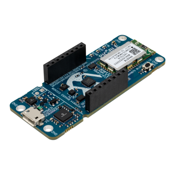
– One logic analyzer channel (DGI GPIO) • USB or Battery Powered Board Overview The PIC-BLE development board is a hardware platform that is being used to evaluate the PIC16LF18456 microcontroller and RN4870 BLE module. Figure 1-1. PIC-BLE Development Board Front Side Micro-USB... - Page 4 PIC-BLE Introduction Figure 1-2. PIC-BLE Development Board Back Side CR2032 Battery Holder Additional RN4870 GPIO User Guide DS50002963B-page 4 © 2020 Microchip Technology Inc.
- Page 5 PIC-BLE Introduction Figure 1-3. PIC-BLE Quick Reference Overview User Guide DS50002963B-page 5 © 2020 Microchip Technology Inc.
-
Page 6: Getting Started
, or Linux device ® and the debug USB port on the PIC-BLE. The board will be identified in the kit window in MPLAB X IDE. Explore, modify, and build off the source code. Make and program the device. Select the PKoB nano serial number as the debug tool when prompted. -
Page 7: Design Documentation And Relevant Links
Tip: If closed, the Kit Window in MPLAB X IDE can be reopened through the menu bar Window > Kit Window. Design Documentation and Relevant Links The following list contains links to the most relevant documents and software for the PIC-BLE board: ® ® ®... -
Page 8: Hardware User Guide
A Data Gateway Interface (DGI) for code instrumentation with logic analyzer channels (debug GPIO) to visualize program flow The on-board debugger controls a Power and Status LED (marked PS) on the PIC-BLE board. The table below shows how the LED is controlled in different operation modes. - Page 9 Baud rate: Must be in the range of 1200 bps to 500 kbps. Any baud rate outside this range will be set to the closest limit, without warning. Baud rate can be changed on-the-fly. • Character format: Only 8-bit characters are supported. User Guide DS50002963B-page 9 © 2020 Microchip Technology Inc.
- Page 10 The default baud rate used in this mode is 9600 bps, but if the CDC is already active or has been configured, the previously used baud rate still applies Debugger firmware version 1.21 and later has the following limitations/features: User Guide DS50002963B-page 10 © 2020 Microchip Technology Inc.
- Page 11 Flash in any way. When programming an Intel HEX file, the binary data are encoded in ASCII with metadata providing a large overhead, so one MB is a trivially chosen value for disk size. User Guide DS50002963B-page 11 © 2020 Microchip Technology Inc.
- Page 12 AUTORUN.ICO – icon file for the Microchip logo • AUTORUN.INF – system file required for Windows Explorer to show the icon file • CLICK-ME.HTM – redirect to the PIC-BLE web demo application • KIT-INFO.HTM – redirect to the development board website •...
- Page 13 X IDE or a stand-alone application that can be used ® in parallel with MPLAB X IDE. Although DGI encompasses several physical data interfaces, the PIC-BLE implementation includes logic analyzer channels: • One debug GPIO channel (also known as DGI GPIO) 3.1.4.1...
-
Page 14: Power Supply
Current drawn from the USB port is limited to 500 mA by a PTC resettable fuse. Important: When powering the PIC-BLE board with a CR2032 battery, it is important to leave the PIC16LF18456 pins that connect to the CDC UART in Tri-State (Input) mode. This is to prevent the debugger from getting powered through its GPIO. -
Page 15: Target Current Measurement
Features such as a 12-bit Analog-to-Digital Converter with Computation (ADC2 ), Memory Access Partitioning (MAP), the Device Information Area (DIA), Power-Saving Operating modes, and Peripheral Pin Select (PPS) offer flexible solutions for a wide variety of custom applications. User Guide DS50002963B-page 15 © 2020 Microchip Technology Inc. - Page 16 +3.3V VBUS The PIC-BLE board features a mikroBUS socket for expanding the functionality of the development board using the MikroElektronika Click board and other mikroBUS add-on boards. The socket is populated with two 1x8 2.54 mm pitch female headers and is ready to mount add-on boards.
- Page 17 ERR LED must be controlled by the user. Both LEDs can be configured for several other functions. Many of the other RN4870 GPIO pins are available as pads around the label on the backside of the PIC-BLE board, as can be...
- Page 18 Microchip CryptoAuthentication products, the ATECC608A employs ultra-secure, hardware-based cryptographic key storage and cryptographic countermeasures that eliminate any potential backdoors linked to software weaknesses. The ATECC608A CryptoAuthentication device on the PIC-BLE board can be used to authenticate the board with other hardware for secure IoT communication.
- Page 19 The Bosch BMA253 is a low-g acceleration sensor with digital output for measurements of acceleration in three perpendicular axes. Additional features: • 12-Bit sensitivity • User selectable acceleration ranges: ±2g, ±4g, ±8g, ±16g • On-chip 32 frame First-In First-Out (FIFO) • Motion triggered interrupts: User Guide DS50002963B-page 19 © 2020 Microchip Technology Inc.
- Page 20 LEDs There is one user LED available on the PIC-BLE board that can be controlled by either GPIO or PWM. Also, there are two LEDs connected directly to the BLE module. The LEDs can be activated by driving their connected I/O lines to GND.
- Page 21 On-board debugger Info: The SW0 signal is pulled up by an external resistor. 3.5.10 On-Board Debugger Implementation PIC-BLE features an on-board debugger that can be used to program and debug the PIC16LF18456 using In-Circuit ™ ™ Serial Programming (ICSP ). The on-board debugger also includes a virtual serial port (CDC) interface over UART ®...
-
Page 22: Hardware Revision History And Known Issues
Identifying Product ID and Revision ® There are two ways to find the revision and product identifier of the PIC-BLE: Either by utilizing the MPLAB X IDE Kit Window or by looking at the sticker on the bottom side of the PCB. -
Page 23: Document Revision History
Doc. rev. Date Comment 11/2020 Document updated with the latest information. Steps describing how to download and install the latest demonstration firmware added to the Quick Start section. 03/2020 Initial document release User Guide DS50002963B-page 23 © 2020 Microchip Technology Inc. -
Page 24: Appendix
PIC-BLE Appendix Appendix Schematics Figure 6-1. PIC-BLE Target schematic User Guide DS50002963B-page 24 © 2020 Microchip Technology Inc. - Page 25 PIC-BLE Appendix Figure 6-2. PIC-BLE Power Schematic User Guide DS50002963B-page 25 © 2020 Microchip Technology Inc.
- Page 26 PIC-BLE Appendix Figure 6-3. PIC-BLE Debugger Schematic User Guide DS50002963B-page 26 © 2020 Microchip Technology Inc.
-
Page 27: Assembly Drawing
PIC-BLE Appendix Assembly Drawing Figure 6-4. PIC-BLE Assembly Drawing Top ® PIC-BLE ® Figure 6-5. PIC-BLE Assembly Drawing Bottom User Guide DS50002963B-page 27 © 2020 Microchip Technology Inc. -
Page 28: The Microchip Website
Attempts to break Microchip’s code protection feature may be a violation of the Digital Millennium Copyright Act. If such acts allow unauthorized access to your software or other copyrighted work, you may have a right to sue for relief under that Act. User Guide DS50002963B-page 28 © 2020 Microchip Technology Inc. -
Page 29: Legal Notice
The Adaptec logo, Frequency on Demand, Silicon Storage Technology, and Symmcom are registered trademarks of Microchip Technology Inc. in other countries. GestIC is a registered trademark of Microchip Technology Germany II GmbH & Co. KG, a subsidiary of Microchip Technology Inc., in other countries. -
Page 30: Quality Management System
PIC-BLE Quality Management System For information regarding Microchip’s Quality Management Systems, please visit www.microchip.com/quality. User Guide DS50002963B-page 30 © 2020 Microchip Technology Inc. -
Page 31: Worldwide Sales And Service
New York, NY Tel: 46-31-704-60-40 Tel: 631-435-6000 Sweden - Stockholm San Jose, CA Tel: 46-8-5090-4654 Tel: 408-735-9110 UK - Wokingham Tel: 408-436-4270 Tel: 44-118-921-5800 Canada - Toronto Fax: 44-118-921-5820 Tel: 905-695-1980 Fax: 905-695-2078 User Guide DS50002963B-page 31 © 2020 Microchip Technology Inc.
Need help?
Do you have a question about the PIC-BLE and is the answer not in the manual?
Questions and answers