Table of Contents
Advertisement
Quick Links
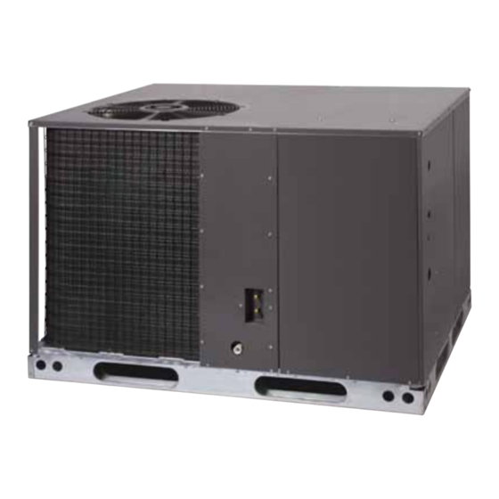
14 SEER Single Package Heat Pump
Installation Instructions
IMPORTANT
These instructions are primarily intended to assist qualified individuals expe-
rienced in the proper installation of heating and/or air conditioning appliances.
Some local codes require licensed installation/service personnel for this type
equipment. All installations must be in accordance with these instructions and
with all applicable national and local codes and standards.
Read these instructions thoroughly before starting the installation. Follow all
precautions and warnings contained within these instructions and on the unit.
Advertisement
Table of Contents

Related Manuals for Nortek Q4SE-X24/PPH1SE


Summary of Contents for Nortek Q4SE-X24/PPH1SE
- Page 1 14 SEER Single Package Heat Pump Installation Instructions IMPORTANT These instructions are primarily intended to assist qualified individuals expe- rienced in the proper installation of heating and/or air conditioning appliances. Some local codes require licensed installation/service personnel for this type equipment.
-
Page 3: Table Of Contents
Table of Contents Section 1. Owner Information ..........4 Operating Instructions .............5 Specifications ................5 Safety Considerations ..............6 Installation Requirements ............6 Dimensions ................7 Unit Installation .................8 Air Ducts ..................9 Electrical Wiring ..............10-11 Optional Humidistat ...............12 Optional Comfort Alert ............13-16 Start Up and System Check ...........17 Optional Outdoor Thermostat..........17 Unit Maintenance ..............18 Wiring Diagrams ..............20-21... -
Page 4: Section 1. Owner Information
SECTION 1. OWNER INfORMATION WINTER HEATINg SUMMER COOlINg 1. Outdoor air enters the heat pump. 1. Indoor air enters the return air duct. 2. The cold, heat-transfer section (outdoor coil) 2. The cold, heat-transfer section (indoor coil) extracts the heat from the air as the refrigerant extracts the heat from the air as the refrigerant evaporates from a liquid to a cold gas. -
Page 5: Operating Instructions
OPERATINg INSTRUCTIONS Defrost — During cold weather heating operation, the outdoor until will develop a coating of snow and ice on the heat transfer coil. This is normal To Operate Your Heat Pump for Cooling — and the unit will periodically defrost itself. During the defrost cycle, the outdoor fan will stop, while 1. -
Page 6: Safety Considerations
INSTAllATION REQUIREMENTS SAfETY CONSIDERATIONS Equipment Check — Before beginning the It is the responsibility of the installer to ensure installation, verify that the unit model is correct for that the installation is made in accordance with the job. The unit model number is printed on the all applicable local and national codes. -
Page 7: Dimensions
24 9/10 3/4" NPT female Drain Connector DOWNflOW SUPPlY DUCT OPENINg 47 1/2 13 1/2 13 1/2 13 3/10 23 1/2 DOWNflOW RETURN DUCT OPENINg Top View 1 4/5 1 3/4 Ø Power Entry (Capped) 1 1/4 Ø Power Entry HORIZONTAl SUPPlY DUCT 22/25 Ø... -
Page 8: Unit Installation
72" 36" 36" 36" 0" figure 4. Minimum Clearances Air filters — A suitable air filter must be installed Rigging and Hoisting — The unit should be lifted in the return air system. Air filter pressure drop using slings and spreader bars. The spreader bars must not exceed 0.08 inches w.c. -
Page 9: Air Ducts
AIR DUCTS WARNINg: This unit is designed only for use with a supply To avoid the risk of property damage and return duct. Air ducts should be installed in or personal injury; it is the rigger’s accordance with the standards of the National Fire Protection Association “Standard for responsibility to insure that whatever Installation of Air Conditioning Systems”... -
Page 10: Electrical Wiring
Acoustical Duct Work — Certain installations WARNINg: may require the use of acoustical lining inside the supply duct work. Acoustical insulation must To avoid the risk of electrical shock, be in accordance with the current revision of the Sheet Metal and Air Conditioning Contractors personal injury, or death, disconnect National Association (SMACNA) application all electrical power to the unit before... - Page 11 Basic Air-flow Setting 1/2 HP Motor 1/2 HP Motor 3/4 HP Motor SWITCH Nominal SWITCH Nominal SWITCH Nominal 1080 1395 1200 1485 1215 1550 1260 1620 1320 1650 1350 1705 1395 1710 1035 1400 1800 1050 1485 1815 1150 1540 1900 1155 1550...
-
Page 12: Optional Humidistat
Selecting the Basic Cooling/Heat Pump and shut-down characteristics of the packaged Airflow— The basic cooling/heat-pump airflow heat pump unit. By varying the start-up and is selected by setting switches 1 through 4 shut-down characteristics of the packaged heat on the thermostat input board located on the pump unit the system can be optimized for energy blower. -
Page 13: Optional Comfort Alert
common (C) wire need not be routed through the module for it to operate properly. CAUTION: UNIT MAINTENANCE To avoid personal injury or property Thermostat Second Stage Cooling Wiring damage, make certain that the motor This Comfort Alert module requires a two leads cannot come into contact with stage thermostat to operate properly. - Page 14 DC SOl Connection Troubleshooting The Installation The two pin DC SOL connector provides a Depending on the system configuration, some connection to the Copeland UltraTech second ALERT Flash codes may not be active. The stage compressor solenoid. This solenoid is presence of safety switches affects how the internal to the compressor.
- Page 15 Status lED Status lED Description Status lED Trouble shooting Information Green “POWER” Module has power Supply voltage is present at module terminals Red “TRIP” Thermostat demand signal “Y” 1. Compressor protector is open • Check for high head pressure is present, but the compressor •...
- Page 16 Status lED Status lED Description Status lED Trouble shooting Information Yellow “AlERT” Short Cycling 1. Thermostat demand signal is intermittent flash Code 3 Compressor is running 2. Time delay relay or control board defective only briefly 3. If high pressure switch present go to Flash Code 2 information 4.
-
Page 17: Start Up And System Check
• Verify that the line voltage power leads are The defrost board is equipped with a 5 minute securely connected and the unit is properly Anti-Short Cycle Delay (ASCD). The compressor grounded. will not turn on until the minimum 5 minute off time is reached. -
Page 18: Unit Maintenance
2. After allowing the unit to run for several equipment. Under no circumstances minutes, set the temperature selector should the owner attempt to install above room temperature. and/or service this equipment. failure - The fan and compressor cycles off with to comply with this warning could the thermostat. - Page 19 Optional Outdoor Thermostat Terminal Block Accessory Heat Plug Brown Orange INDOOR Demand Defrost Board THERMOSTAT SUB-BASE Typical Wiring (field Supplied) for 2-Stage Cool, 1 Stage Electric Heat INDOOR THERMOSTAT SUB-BASE Terminal Block Accessory Heat Plug Brown Orange Optional Outdoor Demand Defrost Board Thermostat Typical Wiring (field Supplied) for 2-Stage Cool, 2-Stage Electric Heat with an Optional Outdoor Thermostat...
-
Page 20: Wiring Diagrams
7108420 figure 9. Two Stage Cool, Two Stage Heat... - Page 21 7108430 figure 9a. Two Stage Cool, Two Stage Heat with Optional Comfort Alert...
-
Page 22: Charging Charts
CHARgINg CHARTS COOlINg - 14 SEER H.P. Q4SE-X24 Charging Chart Q4SE-X24 Charging Chart - Cooling Remove refrigerant when above curve Add refrigerant when below curve Liquid Temperature (F) Q4SE-X36 Charging Chart Q4SE-X36 Charging Chart - Cooling Remove refrigerant when above curve Add refrigerant when below curve Liquid Temperature (F) - Page 23 CHARgINg CHARTS COOlINg - 14 SEER H.P. (CONTINUED) Q4SE-X48 Charging Chart Q4SE-X48 Charging Chart - Cooling Remove refrigerant when above curve Add refrigerant when below curve Liquid Temperature (F) Q4SE-X60 Charging Chart Q4SE-X60 Charging Chart - Cooling Remove refrigerant when above curve Add refrigerant when below curve Liquid Temperature (F)
- Page 24 INSTAllER: PlEASE lEAVE THESE INSTAllATION INSTRUCTIONS WITH THE HOMEOWNER. 7089440 (Replaces 708626B) ¢708944D¤ Specifications and illustrations subject to change without notice and without incurring obligations. Printed in U.S.A. (09/08)
Need help?
Do you have a question about the Q4SE-X24/PPH1SE and is the answer not in the manual?
Questions and answers