Table of Contents
Advertisement
Available languages
Available languages
Quick Links
This manual is intended to meet the Manufacturer's Instructions as required by ANSI Z359 and should be used as part of an
employee training program as required by OSHA. This manual assumes the user has received training in the use of this
equipment.
This product is part of a personal fall arrest, restraint, work positioning, suspension, or rescue system. A Personal Fall Arrest
System (PFAS) is typically composed of an anchorage and a Full Body Harness (FBH), with a connecting device, i.e., a Shock
Absorbing Lanyard (SAL), or a Self‐Retracting Device (SRD), attached to the dorsal D‐ring of the FBH.
Provide these instructions to the user of this equipment. The user must read and understand the manufacturer's instructions
for each component or part of the complete system. Follow manufacturer's instructions for proper use, care, and
maintenance of this product. Retain these instructions and keep them available for the user's reference at all times.
Alterations or misuse of this product, or failure to follow instructions, may result in serious injury or death.
A Fall Protection Plan must be on file and available for review by all users. It is the responsibility of the user and the
purchaser of this equipment to assure that users of this equipment are properly trained in its use, maintenance, and storage.
Training must be repeated at regular intervals. Training must not subject the trainee to fall hazards.
When this equipment is in use the employer must have a rescue plan and the means at hand to implement it and
communicate that plan to users, authorized persons, and rescuers.
Consult a doctor if there is reason to doubt your fitness to safely absorb the shock of a fall event. Age and fitness seriously affect
a worker's ability to withstand falls. Pregnant women or minors must not use this equipment.
NOTE: For more information consult ANSI Z359
User Instruction Manual
Toggle Grip Anchor for Steel
WARNING
1306 South Alameda Street
Compton, CA 90221, USA
1‐800‐719‐4619
1‐323‐752‐0066
www.falltech.com
©2014
MANC23
081314
Advertisement
Table of Contents

Subscribe to Our Youtube Channel
Related Manuals for Falltech 7408


Summary of Contents for Falltech 7408
- Page 1 User Instruction Manual Toggle Grip Anchor for Steel This manual is intended to meet the Manufacturer's Instructions as required by ANSI Z359 and should be used as part of an employee training program as required by OSHA. This manual assumes the user has received training in the use of this equipment. WARNING This product is part of a personal fall arrest, restraint, work positioning, suspension, or rescue system. A Personal Fall Arrest System (PFAS) is typically composed of an anchorage and a Full Body Harness (FBH), with a connecting device, i.e., a Shock Absorbing Lanyard (SAL), or a Self‐Retracting Device (SRD), attached to the dorsal D‐ring of the FBH. Provide these instructions to the user of this equipment. The user must read and understand the manufacturer's instructions for each component or part of the complete system. Follow manufacturer's instructions for proper use, care, and maintenance of this product. Retain these instructions and keep them available for the user’s reference at all times. Alterations or misuse of this product, or failure to follow instructions, may result in serious injury or death. A Fall Protection Plan must be on file and available for review by all users. It is the responsibility of the user and the purchaser of this equipment to assure that users of this equipment are properly trained in its use, maintenance, and storage. Training must be repeated at regular intervals. Training must not subject the trainee to fall hazards. When this equipment is in use the employer must have a rescue plan and the means at hand to implement it and communicate that plan to users, authorized persons, and rescuers. Consult a doctor if there is reason to doubt your fitness to safely absorb the shock of a fall event. Age and fitness seriously affect a worker’s ability to withstand falls. Pregnant women or minors must not use this equipment. NOTE: For more information consult ANSI Z359 1306 South Alameda Street Compton, CA 90221, USA 1‐800‐719‐4619 1‐323‐752‐0066 www.falltech.com ©2014 MANC23 081314 ...
- Page 2 3.1 Capacity 6.1 Storage 3.2 Compatibility of Connectors 6.2 Remove From Service 3.3 Compatibility of Components 7. INSPECTION 3.4 Making Connections 8. LABELS 3.5 Personal Fall Arrest System Appendix A ‐ Table 1, Figures 1 – 4 3.6 Definitions Appendix B ‐ 4. INSTALLATION AND OPERATION 1. DESCRIPTION The FallTech® Toggle Grip Anchor for Steel discussed in this manual is designed to provide a fall protection anchorage for one person working at height and subject to fall hazards. This manual contains two appendices, Appendix A and Appendix B. Appendix A contains tables and figures specific to the Toggle Grip Anchor for Steel. Appendix B contains tables and figures for fall protection in general. Henceforth, all figure and table references in this manual are to Appendix A unless stated otherwise. The anchor is composed of zinc plated alloy steel, and features an attachment eye, a spring‐loaded finger‐pull sleeve surrounding an inner barrel with an integrated swiveling toggle plate. See Figure 1 and Table 1 in Appendix A. For purposes of this manual Toggle Grip Anchor for Steel may be referred to as the toggle grip anchor, the anchor, the product, the equipment, or the unit. The toggle grip anchor is designed to be temporary and reusable, used and moved at will, provided it has not been subjected to fall arrest forces and passes inspection as described in Section 7 of this manual. The anchor discussed in this manual is ANSI Z359.1‐2007 compliant and meets all applicable OSHA 1926.502 regulations. 2. APPLICATION 2.1 Purpose: The Toggle Grip Anchor is designed to be used as single person anchor point for a PFAS to protect the user in a fall event, and as a fall hazard restraint anchor. The small size of the sleeve and toggle allows it to be installed through drilled or cut holes in steel girders, beams or plates. DO NOT use the anchor to lift tools or materials. 2.1.1 Personal Fall Arrest System Application: A PFAS typically includes an anchorage, a Full Body Harness (FBH), and a deceleration device such as a SAL, an SRD, or a Fall Arrestor Connecting Subsystem (FACSS) when used with a fall arrester/SAL. Maximum permissible free fall is six feet. See Figure 2. ...
-
Page 3: Specifications
3.5 Personal Fall Arrest System: PFAS used with the Toggle Grip Anchor must meet ANSI Z359 requirements and applicable OSHA regulations. An anchorage selected for PFAS must be able to sustain a static load applied in the direction permitted by the PFAS of at least: a) Two times the maximum arrest force permitted when certification exists, or b) 5,000 lbs., (22.2 kN) in the absence of certification. An FBH must be worn when this equipment is used as a component of a PFAS. As required by OSHA, the PFAS must be able to arrest the user’s fall with a maximum arresting force of 1,800 lbs., and in this application limit free fall to 6 feet or less. If the maximum free fall distance must be exceeded, the employer must document, based on test data, that the maximum arresting force will not be exceeded, and the personal fall arrest system will function properly. 3.6 Definitions: The following are definitions of terms. Authorized Person: A person assigned by the employer to perform duties at a location where the person will be exposed to a fall hazard (otherwise referred to as “user” for the purpose of these instructions). Certified Anchorage: An anchorage for fall arrest, positioning, restraint, or rescue systems that a qualified person certifies to be capable of supporting the potential fall forces that could be encountered during a fall or that meet the criteria for a certified anchorage prescribed in this standard. Competent Person: One who is capable of identifying existing and predictable hazards in the surroundings or working conditions which are unsanitary, hazardous, or dangerous to employees, and who has authorization to take prompt corrective measures to eliminate them. Qualified Person: A person with a recognized degree or professional certificate and with extensive knowledge, training, and experience in the fall protection and rescue field who is capable of designing, analyzing, evaluating and specifying fall protection and rescue systems to the extent required by this standard. Rescuer: Person or persons other than the rescue subject acting to perform an assisted rescue by operation of a rescue system. 4. INSTALLATION AND OPERATION DO NOT use any anchorage discussed in this manual until the system has been completely installed, inspected, and approved for use by a competent person. NOTE: Approved fall protection may be required during installation of all anchors discussed in this manual. 4.1 Fall Clearance Distance: Take action to reduce the danger of falls. Ensure sufficient clearance in the fall area to arrest the fall before striking the ground or other objects. The actual clearance required is dependent upon the type of connecting subsystem used (SAL, SRD, etc.). Swing fall conditions will increase the Clear Fall requirement. See Figure 1, Figure 3, and Figure 4 in Appendix B. 4.2 Swing Fall: Swing falls occur when the anchorage point is not directly above the point where a fall occurs. The total fall distance may be greatly increased during a swing fall. The force of striking an object in a swing fall may cause serious injury. Eliminate swing falls by working as directly below the anchorage as possible. Note the location on the walking/working surface that is directly under the anchor. That location is the center of the work zone. Work as closely as possible to the center of the work zone. Lateral movement away from the center will increase swing fall. If it is necessary to move away from the work zone center, do not exceed the 30° angle formed by the lifeline and the device in use. See Figure 3. 4.3 Install the Anchor: Ensure the chosen location will meet the strength requirements detailed in Section 3 of this manual. Ensure the chosen location will minimize free fall and swing fall hazards detailed in paragraphs 4.1 and 4.2. The anchor is designed to be passed through an overhead installation hole from below and to be used in a vertical application. WARNING The Toggle Grip Anchor is not intended for use in a horizontal application. Use of the anchor in a horizontal application will place non‐design loads on the anchor. Such loads could result in damage to the anchor and serious injury or death to the user. The installation hole must be a minimum of 13/16", and a maximum of 1‐1/4". Ensure the hole is free of jagged, rough or abrasive edges. ... - Page 4 Inspect for: 1. cracks or fractures 2. severe or excessive abrasion any place on the unit 3. corrosion 4. a build‐up of contaminants 5. thermal or electric arc damage If routine inspection reveals damage to the anchor, discontinue use and remove it from service. Record inspection results on the Inspection Record found in Appendix B or on any suitable record. 8. LABELS The following labels must be present and legible: ...
- Page 5 Anclaje de sujeción articulado para acero Este manual tiene como objetivo cumplir con las instrucciones del fabricante como lo exige ANSI Z359 y debe utilizarse como parte de un programa de capacitación de empleados como lo exige la OSHA. Este manual entiende que el usuario ha recibido capacitación en el uso de este equipo. ADVERTENCIA Este producto forma parte de un sistema personal de detención de caídas, restricción, posicionamiento del trabajo, suspensión o rescate. Un Sistema personal de detención de caídas (PFAS, por su siglas en inglés) se compone, generalmente, por un anclaje y un Arnés de cuerpo completo (FBH, por sus siglas en inglés) con un dispositivo de conexión, por ejemplo una Cuerda amortiguadora (SAL, por sus siglas en inglés) o un Dispositivo retráctil (SRD, por sus siglas en inglés) unido al anillo en "D" dorsal del FBH. Entregue estas instrucciones al usuario de este equipo. El usuario debe leer y comprender las instrucciones del fabricante para cada componente o pieza del sistema completo. Siga las instrucciones del fabricante para el uso, cuidado y mantenimiento de este producto. Conserve estas instrucciones y manténgalas disponibles para referencia del usuario en todo momento. Las alteraciones o el uso incorrecto de este producto o el incumplimiento de las instrucciones pueden provocar lesiones graves o la muerte. Debe haber un Plan de Protección contra caídas archivado y disponible para ser revisado por todos los usuarios. Es responsabilidad del usuario y del comprador de este equipo garantizar que los usuarios de este equipo estén correctamente capacitados para su uso, mantenimiento y almacenamiento. La capacitación debe repetirse cada intervalos regulares. La capacitación no debe poner en peligro de caída al capacitador. Cuando este equipo está en uso, el empleador debe tener un plan de rescate y los medios necesarios para implementarlo y comunicar ese plan a los usuarios, las personas autorizadas y los socorristas. Consulte con un médico si existen motivos para dudar de su capacidad física para absorber de manera segura el impacto en el caso de una caída. La edad y la capacidad física afectan seriamente la capacidad del trabajador de soportar caídas. Las mujeres embarazadas o niños menores no deben utilizar este equipo. NOTA: para obtener información adicional, consulte ANSI Z359 1306 South Alameda Street Compton, CA 90221, USA 1‐800‐719‐4619 1‐323‐752‐0066 www.falltech.com ©2014 ...
-
Page 6: Requisitos Del Sistema
MANTENIMIENTO ALMACENAMIENTO 3.1 Capacidad 6.1 Almacenamiento 3.2 Compatibilidad de los conectores 6.2 Retiro del servicio 3.3 Compatibilidad de los componentes 7 INSPECCIÓN 3.4 Establecimiento de conexiones 8 ETIQUETAS 3.5 Sistema de detención de caídas personales Apéndice A ‐ Tabla 1, Figuras 1 – 4 3.6 Definiciones Apéndice B ‐ 4. INSTALACIÓN Y FUNCIONAMIENTO 1 DESCRIPCIÓN El anclaje de sujeción articulado para acero FallTech® de este manual está diseñado para brindar un anclaje de protección contra caídas para una persona que trabaja en altura y está expuesta al peligro de caídas. Este manual contiene dos apéndices, Apéndice A y Apéndice B. El Apéndice A contiene tablas y figuras específicas del anclaje de sujeción articulado para acero. El Apéndice B contiene tablas y figuras para la protección contra caídas en general. De aquí en adelante, todas las referencias a figuras y tablas en este manual corresponden al Apéndice A, a menos que se indique lo contrario. El anclaje está hecho de acero aleado cincado y cuenta con un ojillo de fijación, un pestillo con resorte tirador alrededor de un barril interno con una placa articulada giratoria integrada. Consulte la Figura 1 y la Tabla 1 en el Apéndice A. Para los fines de este manual, puede hacerse referencia al anclaje de sujeción articulado para acero como el anclaje de sujeción articulado, el anclaje, el producto, el equipo o la unidad. El anclaje de sujeción articulado está diseñado para tener un uso temporal y ser reutilizado, para utilizarlo y transportarlo a gusto ya que no se lo ha sometido a fuerzas de detención de caída y aprobó la inspección como se describe en la Sección 7 de este manual. El anclaje que se trata en este manual es ANSI Z359. Cumple con 1‐2007 y con todas las normativas aplicables OSHA 1926.502. 2 APLICACIÓN 2.1 Finalidad: El anclaje de sujeción articulado está diseñado para ser utilizado como punto de anclaje para una sola persona como PFAS para proteger al usuario en el caso de una caída y como anclaje de restricción de peligro de caída. El tamaño pequeño del pestillo y la articulación permiten que se instale a través de orificios perforados o cortados en vigas, viguetas o placas de acero. NO utilice el anclaje para elevar herramientas o materiales. 2.1.1 Aplicación del sistema de detención de caídas personales: Un PFAS generalmente incluye un anclaje, un Arnés de cuerpo completo (FBH) y un dispositivo de desaceleración como un SAL, un SRD, o un Subsistema de conexión de detenedor de caídas (FACSS, por sus siglas en inglés) cuando se utiliza con un Detenedor de caídas/SAL. La caída libre máxima permitida son 6 pies (1,8 m). Consulte la Figura 2. ... -
Page 7: Instalación Y Funcionamiento
3.4 Establecimiento de conexiones: Utilice solo conectores diseñados para utilizar con este equipo, adecuados para cada aplicación. Asegúrese de que todas las conexiones sean compatibles en tamaño y dureza. No utilice equipos que no sean compatibles. Asegúrese visualmente de que todos los conectores estén totalmente cerrados y bloqueados. Asegúrese de que los ganchos de cierre instantáneo y los mosquetones utilizados con este producto estén cargados y alineados con el eje principal. Consulte el manual de instrucciones para el usuario de cada producto. 3.5 Sistema de detención de caídas personales: Un PFAS utilizado con un anclaje de sujeción articulado debe cumplir con los requisitos ANSI Z359 y las normativas aplicables de la OSHA. Un anclaje seleccionado para PFAS debe ser capaz de sostener una carga estática aplicada en el sentido permitido por el PFAS de, por lo menos: a) Dos veces la fuerza de detención máxima permitida si existe la certificación, o b) 5.000 libras (22,2 kN) si no se cuenta con la certificación. Debe utilizarse un FBH cuando se utiliza este equipo como componente de un PFAS. Tal como lo requiere la OSHA, el PFAS debe poder detener la caída del usuario con una fuerza de detención máxima de 1.800 libras (817 kg) y en esta aplicación limitar la caída libre a 6 pies (1,8 m) o menos. Si debe excederse la distancia de caída libre, el empleador debe documentar, sobre la base de datos de prueba, que la fuerza de detención máxima no se excederá y que el sistema de detención de caídas funcionará correctamente. 3.6 Definiciones: Las siguientes son definiciones de términos. Persona autorizada: una persona designada por el empleador para realizar tareas en un lugar donde la persona estará expuesta al peligro de caída (también referido como “usuario” a los fines de estas instrucciones). Anclaje certificado: un anclaje para detención de caídas, posicionamiento, restricción o sistemas de rescate que una persona calificada certifica poder soportar las posibles fuerzas de una caída que podría sufrir durante una caída o cumplir los criterios para un anclaje certificado prescrito en esta norma. Persona competente: persona capaz de identificar peligros existentes y predecibles en el entorno o condiciones laborales que sean insalubres, riesgosas o peligrosas para los empleados y que está autorizada a tomar medidas correctivas rápidas para eliminarlas. Persona calificada: persona con un título reconocido o un certificado profesional y con conocimientos, capacitación y vasta experiencia en el campo de la protección contra caídas y rescate capaz de diseñar, analizar, evaluar y especificar sistemas de protección contra caídas y rescate en la medida requerida por esta norma. Socorrista: persona o personas aparte del sujeto de rescate que actúan para llevar a cabo un rescate asistido a través de un sistema de rescate. 4 INSTALACIÓN Y FUNCIONAMIENTO NO utilice ningún anclaje que se menciona en este manual hasta que el sistema se haya instalado, inspeccionado y aprobado para el uso de una persona competente. NOTA: puede requerirse protección contra caídas aprobada durante la instalación de todos los anclajes mencionados en este manual. 4.1 Distancia despejada de caída: Tome medidas para reducir el peligro de caídas. Asegure una distancia despejada suficiente en el área de caídas para detener la caída antes de golpearse con el piso u otros objetos. La distancia despejada real requerida depende del tipo de subsistema de conexión utilizado (SAL, SRD, etc.). Las condiciones de caída con balanceo aumentarán el requisito de caída despejada. Consulte la Figura 1, Figura 3 y Figura 4 en el Apéndice B. 4.2 Caída con balanceo: Las caídas con balanceo ocurren cuando el punto de anclaje no se encuentra directamente encima del punto donde ocurre la caída. La distancia de caída total puede aumentar mucho durante una caída con balanceo. La fuerza con la que se golpea un objeto en una caída con balanceo puede provocar lesiones graves. Elimine las caídas con balanceo trabajando directamente debajo del anclaje en la medida de lo posible. Tenga en cuenta la ubicación en la superficie donde camina/trabaja directamente debajo del anclaje. Esa ubicación es el centro de la zona de trabajo. Trabaje lo más cerca posible del centro de la zona de trabajo. El movimiento lateral fuera del centro aumentará la caída con balanceo. Si es necesario moverse del centro de la zona de trabajo, no exceda el ángulo de 30° formado por la cuerda de salvamento y el dispositivo en uso. Consulte la Figura 3. ... - Page 8 6.1 Almacenamiento: Cuando no esté instalado, almacenar en un área limpia y seca. Evite la luz del sol directa y la exposición a elementos medioambientales. No coloque otros equipos u objetos arriba de los anclajes. No almacene de manera tal que permita que otro equipo se doble, rompa, contamine o dañe la unidad. 6.2 Retiro del servicio: Retire el anclaje del servicio si ha estado sometido a fuerzas de detención de caídas o si falla la inspección. 7 INSPECCIÓN DEL ANCLAJE DE SUJECIÓN ARTICULADO Antes de cada uso, el usuario debe inspeccionar que el anclaje no tenga daños físicos, desgaste, corrosión o piezas faltantes. Si un anclaje se ha sometido a fuerzas de detención de caída, debe retirarse del servicio. Inspeccione que no haya lo siguiente: 1. Grietas o fracturas. 2. Abrasión grave o excesiva en cualquier parte de la unidad. 3. Corrosión. 4. Una acumulación de elementos contaminantes. 5. Daño térmico o de arco eléctrico. Si la inspección de rutina revela daños al anclaje, suspenda el uso y retire del servicio. Registre los resultados de la inspección en el Registro de Inspección que se encuentra en el Apéndice B o en cualquier registro adecuado. 8 ETIQUETAS Las siguientes etiquetas deben estar presentes y ser legibles: ...
- Page 9 Table 1: Specifications for Toggle Grip Anchor Maximum Minimum Part User Dimensions Tensile Strength Anchor Number Capacity and Material 310 lbs 7408 to comply with Length: ANSI Z359.1, Toggle 9-1/4” 2007 5,000 lbs Grip Anchor and OSHA 1926.502 Connection Eye:...
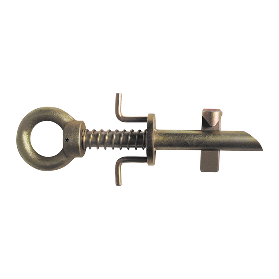
- Page 10 Figure 1: About Toggle Grip Anchor Figura 1: Acerca del Anclaje de sujeción articulado Forged Connector Eye Ojillo conector forjado Compression Spring Resorte de compresión Finger Pull Grips Sujeción del tirador Green Indicator Band Banda indicadora verde Spring Compressing Plate Placa de compresión del resorte Insertion Barrel Barril de inserción...
- Page 11 Figure 2: Applications of Fall Protection Use Figura 2: Aplicaciones de uso de protección contra caídas Fall Arrest with Shock Absorbing Lanyard Detención de caídas con cuerda amortiguadora Fall Arrest with Self Retracting Lifeline Detención de caídas con cuerda de salvamento retráctil Fall Arrest with FACSS Detención de caídas con FACSS Fall Restraint with Restraint Lanyard...
- Page 12 Figure 3: Simple Operation of Toggle Anchor Figura 3: Operación simple de anclaje giratorio Index Finger Pull Tirador de dedo índice Thumb in Eye Pulgar en ojillo Middle Finger Pull Tirador de dedo mayor Toggle Bar Retracts Flat Into Barrel Barra giratoria se retrae en el barril Insert Barrel into Hole with Spring Compressed Inserte el barril en el orificio on el resorte comprimido...
- Page 13 INCORRECT CORRECT INCORRECT CORRECT INCORRECT CORRECT Figure 4: Correct and Incorrect Use for Fall Arrest Figura 4: Uso correcto e incorrecto para detención de caídas Correct- Toggle Bar Released and Locked Correcto: barra giratoria liberada y bloqueada Correct- Through I-Beam Flange Correcto: a través de reborde de perfil doble “T”...
- Page 14 APPENDIX B Fig. 1 - Minimum Clear Fall Requirement: 6 ft Shock Absorbing Lanyard Measured from Overhead Anchorage Connector Length of Shock Absorbing Lanyard Original working length before a fall event occurs/before acti ation of energy absorber Elongation/Deceleration Distance Maximum allowable amount of elongation th t may payout from the energy absorber upon acti ation during a all event Harness Stretch and Dorsal D-Ring Shift Combined amount of harness webbing elongation and dorsal back D-ring...
- Page 15 Fig. 3 - Minimum Clear Fall Requirement: ANSI Class A Self-Retracting Device Activation/Deceleration Distance Maximum allowable length of cable or web that may payout from the SRD once deceleration of the user has begun and a er a fall event occurs Harness Stretch and Dorsal D-Ring Shift Combined amount of harness webbing elongation and do sal D-ring up- shift during e ti e fall event...
- Page 16 Fig. 5 - Managing Stretch Minimum Clear Fall Requirement: Verti al Lifeline System Stretch of Vertical Lifeline Stretch Stretch = length of VLL from Anchorage Connector to Rope Grab position on VLL multiplied y 10% Length of Shock Absorbing Lanyard Original working length before a fall event occurs/before acti ation of ene gy absorber Elongation/Deceleration Distance...
- Page 17 Common Fall Protection Applications Fig. 7 - Fall Arrest (PFAS) Fig. 8 - Work Positioning Anchorage Positioning Ancho Anchorage Connector Positioning La yard Full Body Harness (FBH) with Shock Absorbing Lanyard (SAL) Side D-Rings Full Body Harness (FBH) Back-up Fall Arrest (PFAS) Walking/Working Surface Fig.
-
Page 18: Inspection Record
Incorrect Connections / Acronyms for Fall Protection and Fall Arrest / Inspection Record Fig. 13 - Incorrect Connections Fig. 13 - Conexiones incorrectas Never connect two acti e components (snap hooks or carabiners) Nunca conecte dos componentes acti os (ganchos de cierre instantáneo to each other.
Need help?
Do you have a question about the 7408 and is the answer not in the manual?
Questions and answers