Table of Contents
Advertisement
Available languages
Available languages
Quick Links
This manual is intended to meet the Manufacturer's Instructions as required by ANSI Z359 and should be used as part of
an employee training program as required by OSHA.
This product is part of a personal fall arrest, restraint, work positioning, suspension, or rescue system. A Personal Fall
Arrest System (PFAS) is typically composed of an anchorage and a Full Body Harness (FBH), with a connecting device,
i.e., a Shock Absorbing Lanyard (SAL), or a Self-Retracting Device (SRD), attached to the dorsal D-ring of the FBH.
instructions must be provided to the user of this equipment. The user must read and understand the manufacturer's
instructions for each component or part of the complete system. Manufacturer's instructions must be followed for
proper use, care, and maintenance of this product. These instructions must be retained and be kept available for the
user's reference at all times.
Alterations or misuse of this product, or failure to follow instructions, may result in serious injury or death.
A Fall Protection Plan must be on file and available for review by all users. It is the responsibility of the user and the
purchaser of this equipment to assure that users of this equipment are properly trained in its use, maintenance, and
storage. Training must be repeated at regular intervals. Training must not subject the trainee to fall hazards.
Consult a doctor if there is reason to doubt your fitness to safely absorb the shock of a fall event. Age and fitness seriously
affect a worker's ability to withstand falls. Pregnant women or minors must not use this equipment.
Rev C
User Instruction Manual
Leading Edge Cable SRD
WARNING
NOTE: For more information consult ANSI Z359
FallTech
1306 South Alameda Street
Compton, CA 90221, USA
1-800-719-4619
1-323-752-0066
www.Fall Tech.com
©2016
061319
MSRD08
Advertisement
Table of Contents

Subscribe to Our Youtube Channel
Related Manuals for Falltech 727630LE


Summary of Contents for Falltech 727630LE
- Page 1 Consult a doctor if there is reason to doubt your fitness to safely absorb the shock of a fall event. Age and fitness seriously affect a worker’s ability to withstand falls. Pregnant women or minors must not use this equipment. NOTE: For more information consult ANSI Z359 FallTech 1306 South Alameda Street Compton, CA 90221, USA...
-
Page 2: Table Of Contents
1. DESCRIPTION The FallTech® Contractor Leading Edge SRD is a self-retracting device for those working at height and subject to Leading Edge fall hazards. For purposes of this manual, the Contractor Leading Edge SRD in all iterations may be referred to collectively as the SRD, the SRD-Leading Edge (SRD-LE), the self-retracting device, the equipment, the device, the product, or the unit. -
Page 3: System Requirements
Maximum Peak Arresting Force of 1800 lbs, for both ambient and conditioned testing. When dynamically tested in accordance with requirements of ANSI Z359.14-2014, FallTech Class A Self-Retracting Devices have an AAF of 1350 lbs and an AD of less than 24". -
Page 4: Pfas Anchorage Strength
In addition, Table 1B: Typical FallTech Performance and ANSI Performance Attributes provides two lists of test performance attributes, listed by worst case values, and by maximum values of testing, using a 310 lb. weight in both an overhead anchorage condition, and in a non-overhead anchorage conditions. -
Page 5: Calculate Srl-Le Mrfc Anchorage: 0' Setback From Leading Edge And 5' Below The Dorsal D-Ring
D = Dorsal D-Ring Shift and FBH Stretch E = Safety Factor F = Sub Total-Minimum Required Fall Clearance G = Additional Fall Clearance Calculation for Swing Fall – 4' maximum H = Minimum Required Fall Clearance Use Figure 3A as a worksheet. The MRFC for this anchorage geometry is calculated as A+B+C+D+E=F. F is the Sub Total-MRFC. -
Page 6: Inspect The Constituent Cable
A red band is further up the lifeline. The red band, also shown in Figure 7, indicates the reserve portion of the lifeline has been breached. The SRD is no longer safe to us. Remove the SRD from service immediately, tag it as "UNUSABLE", and contact FallTech at info@falltech.com 4.2.4 Inspect the Constituent Cable: The SRD lifeline is steel cable, and subject to certain hazards. - Page 7 8. LABELS All labels must be present and legible. 9. SRD in Non-LE Standard Mode: The Leading Edge SRD may be used may be used as a standard SRD in an overhead condition, in which the SRD is installed anywhere in the allowable attachment area, which ranges from directly above the user to level with the FBH D-ring, as shown in Figure 9A.
- Page 8 La edad y el estado físico afectan gravemente a la capacidad de los trabajadores para soportar caídas. Las mujeres embarazadas y los menores de edad no deben utilizar este equipo. NOTA: Para obtener más información, consulte ANSI Z359 FallTech 1306 South Alameda Street Compton, CA 90221, USA...
- Page 9 APÉNDICE B Figuras 1 – 13, Registro de Inspección 1. DESCRIPCIÓN El Dispositivo auto-retráctil (SRD) para bordes expuestos Contractor de FallTech® es un dispositivo auto-retráctil para personas que trabajan en alturas y están sujetas a peligros de caídas en bordes expuestos.
- Page 10 (816,5 kg), tanto para las pruebas de ambiente como condicionadas. Cuando se prueban dinámicamente de acuerdo con los requisitos de ANSI Z359.14-2014, los Dispositivos auto-retráctiles Clase A de FallTech tienen una Fuerza de detención promedio de 1.350 libras (612,3 kg) y una Distancia de detención de menos de 24" (61 cm).
- Page 11 1435 libras (3.163 kg) Además, en la Tabla 1B: El rendimiento típico de FallTech y los atributos de rendimiento de ANSI establecen dos listas de atributos de rendimiento de prueba, que se indican por valores en el peor de los escenarios, y por los valores máximos de las pruebas, con un peso de 310 libras (140,6 kg) en un anclaje por encima del nivel de la cabeza, y en condiciones de anclaje que no esté...
- Page 12 Tenga cuidado. Tome medidas para evitar las superficies y bordes abrasivos y/o afilados. 4.1. Instalar el SRD: Examine el área de trabajo para detectar los posibles peligros. Tenga cuidado para evitar los peligros por encima del nivel de la cabeza, tales como grúas, polos, y cables de corriente elevados, y peligros en las superficies para caminar/trabajar, tales como cables de corriente, cables para soldar, mangueras de aire y líquidos, incluyendo los peligros de obstrucción, tales como las columnas verticales y las pilas de materiales en el nivel inferior.
- Page 13 Si se saca accidentalmente cuerda de salvamento adicional del SRD sin un evento de caída, se debe retirar el SRD de servicio, etiquetarlo como "INUTILIZABLE", y contactar a FallTech para determinar las opciones. Una banda de color rojo está más arriba de la cuerda de salvamento. La banda roja, también mostrada en la Figura 7, indica que la parte de reserva de la cuerda de salvamento se ha utilizado.
- Page 14 Si se produce una caída, el freno se activará y bloqueará la cuerda de salvamento. El EA se desplegará para detener la caída y limitar las fuerzas de detención sobre el usuario. Comuníquese con FallTech para el servicio en info@falltech.com o al 323-752-0066. El SRD no puede ser reparado por el usuario. NO extienda la cuerda de salvamento después del límite operativo.
- Page 15 8. ETIQUETAS Todas las etiquetas deben estar presentes y legibles. 9. SRD en modo estándar en casos que no sean bordes expuestos: El SRD para bordes expuestos se puede utilizar como un SRD en una condición por encima del nivel de la cabeza, en la cual el SRD se instala en cualquier parte del área de conexión permisible, que oscila entre directamente por encima del usuario a nivel del anillo en "D"...
- Page 16 Capacity and Model # Constituent Weight and SRL-LE Specifications Standards Housing Size 30 ft Housing: 7/32” Glass-Filled 727630LE Galvanized Steel 19.4 lbs Nylon Cable Polycarbonate 10” diameter Anchorage User Capacity: Carabiner: 130 to 310 lbs 5,000 lbs with 3,600 lbs...
- Page 17 Table 1B: FallTech Leading Edge SRL-LE Performance Attributes Part #s and Conditions Typical FallTech Performance ANSI Perfomance Requirements Maximum Average Maximum Arrest Maximum Anchorage Average Part # Arrest Force Arrest Arrest Distance Condition Class Arrest Force Arrest Force Distance *Conditioned...
- Page 18 Tabla 1B: Atributos de rendimiento de SRL-LE para bordes expuestos FallTech No. de partes y condiciones Rendimiento típico de Falltech Requisitos de rendimiento de ANSI Fuerza de Distancia de Fuerza de Fuerza de Fuerza de detención Distancia de Clase de No.
-
Page 19: Maintenance
Table 2 - ANSI Z359.14-2014 SRD Inspection Recommendations Inspection Frequency Type of Use Application Examples Conditions of Use Competent Person Good Storage Conditions, Rescue and Confined Indoor or Infrequent Infrequent to Space, Factory Outdoor use, Room Annually Light Use Maintenance Temperature, Clean Environments Fair Storage Conditions,... - Page 20 Table 3: Guidelines for Cable SRD Inspection (use Figure 1 where needed) Inspection Pass Fail The cable lifeline should extract and retract completely and without faltering and should remain taut under tension without sagging. Extract the cable lifeline several inches and apply a firm pull to confirm the SRD locks.
- Page 21 Tabla 3: Directrices para la inspección del SRD con cable (utilice la Figura 1 donde sea necesario) Inspección Aprobado Fallado La cuerda de salvamento con cable se debe extraer y retraer por completo y sin fallar y debe seguir estando tensa bajo tensión sin aflojarse.
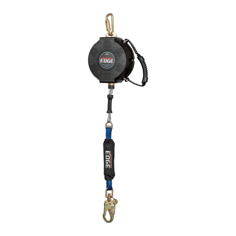
- Page 22 Figure 1: About Contractor Leading Edge SRL-LE Anchorage Connecting Carabiner SRD Unit Housing Cable-Stop/Handle Assembly (spring/bumpers) Integral Leading Edge Energy Absorber Load-indicating Swivel Carabiner Carry Handle Figura 1: Acerca de SRL-LE para bordes expuestos Contractor Mosquetón de conexión del anclaje Carcasa del SRD Ensamblaje de detección del cable/agarre (resorte/paragolpes) Amortiguador de energía integral para bordes expuestos...
- Page 23 Figure 2: Anchorage Range of Leading Edge SRL-LE Anchorage of SRD at Foot Level with 0’ Setback from Leading Edge Anchorage of SRD at Foot Level with 5’ Setback from Leading Edge Overhead Anchorage of SRD Above Dorsal D-Ring with 0’ Setback from Leading Edge Anchorage of SRD Above Dorsal D-Ring with 5’...
- Page 24 Figure 3A: Calculating Minimum Required Fall Clearance SRL-LE Anchorage: 5’ Minimum Setback from Leading Edge and 5’ below Dorsal D-ring 6½ ft SRD Deceleration Distance (Worst Case Value, See Table 1B for Exact Model) Dorsal D-Ring Shift and FBH Stretch 1 ft Combined amount of Dorsal D-ring up-shift and harness webbing elongation during a fall event...
- Page 25 Figura 3A: Cálculo de la distancia mínima de caída despejada requerida del SRL-LE Anclaje: Revés mínimo de 5 pies (1,5 m) desde el borde expuesto y 5 pies (1,5 m) por debajo del anillo en “D” dorsal 6½ pies Distancia de desaceleración del SRD (peor valor de caso, ver tabla 1B para el modelo exacto) (2 m) Tramo del arnés y cambio del anillo en “D”...
- Page 26 Figure 3A: Calculating Minimum Required Fall Clearance SRL-LE Anchorage: 0’ Minimum Setback from Leading Edge and 5’ below Dorsal D-ring 10 ft SRD Deceleration Distance (Worst Case Value, See Table 1B for Exact Model) Dorsal D-Ring Shift and FBH Stretch 1 ft Combined amount of Dorsal D-ring up-shift and harness webbing elongation during a fall event...
- Page 27 Figura 3B: Cálculo de la distancia mínima de caída despejada requerida del SRL-LE Anclaje: Revés de 0 pies desde el borde expuesto y 5 pies (1,5 m) por debajo del anillo en “D” dorsal 10 pies Distancia de desaceleración del SRD (peor valor de caso, ver tabla 1B para el modelo exacto) (3 m) Tramo del arnés y cambio del anillo en “D”...
- Page 28 Figure 4A: Swing Fall Hazard: Leading Edge Condition with 5’ Setback Walking/Working Surface Foot Level Anchorage with 5’ Setback from Leading Edge Expanded Lateral Work Zone with Leading Edge Condition See Chart 1 for additional Swing Fall hazard due to increased Fall Distance Note: 8’...
- Page 29 Chart 1: Additional Fall Clearance Locator due to Swing Fall (feet) with Leading Edge Conditions for 5’ Setback from Leading Edge with Foot Level Anchorage Dorsal D-Ring X- Axis: Lateral Work Zone Radius (ft) Using Chart 1 to Find Additional Fall Clearance: Leading Edge Conditions 2 foot increments along the 5 foot increments up the X-Axis represent the distance the user is working...
- Page 30 Gráfico 1: Localizador de distancia adicional de caída despejada debido a la caída con balanceo (pies) con condiciones de bordes expuestos Para revés de 5 pies (1,5 m) desde el borde expuesto con anclaje al nivel de los pies Anillo en “D”...
- Page 31 Chart 2: Additional Fall Clearance Locator due to Swing Fall (feet) with Leading Edge Conditions for 0’ Setback from Leading Edge with Foot Level Anchorage Dorsal D-Ring X- Axis: Lateral Work Zone Radius (ft) Using Chart 2 to Find Additional Fall Clearance: Leading Edge Conditions 2 foot increments along the 5 foot increments up the X-Axis represent the distance the user is working...
- Page 32 Gráfico 2: Localizador de distancia adicional de caída despejada debido a la caída con balanceo (pies) con condiciones de bordes expuestos Para revés de 0 pies desde el borde expuesto con anclaje al nivel de los pies Anillo en “D” dorsal Eje X: Zona de trabajo lateral (pies/metros) Uso del Gráfico 2 para determinar la distancia adicional de caída despejada:...
- Page 33 Figure 5A: Leading Edge Angle of Lifeline Redirect Ok- 90° Minimum Angle over Leading Edge Ok- Greater than 90° Minimum Angle over Leading Edge Not Ok- less than 90° Angle over Leading Edge Figura 5A: Ángulo del borde expuesto para la redirección de la cuerda de salvamento Adecuado - 90°...
- Page 34 Figure 5B: Typical Extreme Sharp Edge Hazards Structural Steel I-Beams and Purlins Steel Deck and Metal Roofing Poured Concrete and Concrete Block Examples not intended to depict the full extent of all hazardous sharp edges found on jobsites for the User to identify and avoid. Figura 5B: Peligros extremos típicos de bordes expuestos Vigas I de acero estructurales y correas Cubierta de acero y techos de metal...
- Page 35 3/16” 7/37” Figure 5C: Incorrect Use of Leading Edge SRD Do Not subject cable lifeline to Leading or Sharp Edge during normal use Do Not anchor SRD on opposite side of exisiting hole or floor opening from work location Do Not use 3/16” Cable SRDs in Leading Edge Conditions; use only SRL-LE with 7/32”...
- Page 36 Figure 6: Inspecting SRD Load-Indicating Leg-end Connector Regular Safe Operating Condition of Swivel Leg-end Connector Visual Indicator Exposed on Connector - Remove SRD from Service Figura 6: Inspección del conector del extremo de las piernas con indicador de la carga del SRD Condiciones seguras de funcionamiento regular del conector giratorio del extremo de la pierna Indicador visual expuesto en el conector - Retirar el SRD de servicio...
- Page 37 Figure 7: Inspecting SRD Line Indicators Green Indicator- Regular Safe Operating Condition of Cable Lifeline Length Red Indicator- Reserve Line Unprotected; Remove SRD from Service Figura 7: Inspeccionar los indicadores de la cuerda del SRD Indicador verde- Condiciones seguras de funcionamiento regular de la longitud de la cuerda de salvamento con cable Indicador rojo - Cuerda de reserva desprotegida;...
- Page 38 Figure 8: Inspection of Constituent Cable Heat Damage from Weld Spatter or Slag Bird Caged Broken Wires within Strands Curled, Bent or Kinked Figura 8: Inspección del cable componente Daños causados por el calor de las salpicaduras de soldadura o escoria Enrollado Cables rotos con hebras Curvado, doblado o aplastado...
- Page 39 Non-Leading Edge Overhead Conditions Figure 9A: Calculating Required Fall Clearance: SRL-LE Deceleration Distance Maximum allowable length of cable or web that may payout from the SRD 3½ ft once deceleration of the user has begun and after a fall event occurs. For work in low clearance areas, see Table 1B for Typical Performance Dorsal D-Ring Shift and FBH Stretch 1 ft...
- Page 40 Condiciones por encima del nivel de la cabeza sin bordes expuestos Figura 9A: Cálculo de la distancia de caída despejada requerida: SRL-LE Distancia de desaceleración Distancia máxima permitida del cable o red que puede emplearse desde el SRD 3½ pies una vez que la desaceleración del usuario ha comenzado y después de que ocurra (1,06 m) un evento de caída.
- Page 41 Figure 9B: Swing Fall Hazards Non-Leading Edge Anchorage Self-Retracting Lifeline Walking/Working Surface Swing Fall Impact after fall event Next Lower Level or Obstruction See Chart 9 for additional Swing Fall Hazard due to increased fall distance for use with Figure 9A Figura 9B: Peligros de caída con balanceo con bordes no expuestos Anclaje...
- Page 42 Chart 9: Additional Fall Clearance Due to Swing Fall (feet) Overhead Non-Leading Edge Condition Dorsal D-Ring X- Axis: Lateral Work Zone Radius (ft) Using Chart 9 to Find Additional Fall Clearance: Overhead Non-Leading Edge 2 foot increments along the X-Axis represent the 5 foot increments up the distance the user is working away from being Y-Axis represent the SRD Anchorage height...
- Page 43 Gráfico 9: Distancia adicional de caída despejada debido a la caída con balanceo (pies) con condiciones que no sean de bordes expuestos Anillo en “D” dorsal Eje X: Zona de trabajo lateral (pies/metros) Uso del Gráfico 9 para determinar la distancia adicional de caída despejada: Borde no expuesto Los incrementos de 2 pies (0,6 m) a lo largo Los incrementos de 5 pies (1,5 m) arriba del eje...
Need help?
Do you have a question about the 727630LE and is the answer not in the manual?
Questions and answers