Table of Contents
Advertisement
Quick Links
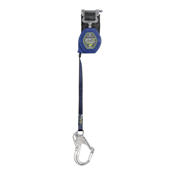
DuraTech Class 2 Leading Edge SRL
User Instruction Manual
This manual is intended to meet the Manufacturer's Instructions as required by the American National Standards
Institute (ANSI) Z359 and should be used as part of an employee training program as required by the Occupational
Safety and Health Administration (OSHA).
MSRD28 Rev B
FallTech 1306 S. Alameda Street Compton, CA 90221, USA Tel: 800-719-4619 Fax: 323-752-5613
081723
Advertisement
Table of Contents


Need help?
Do you have a question about the DuraTech Class 2 Leading Edge SRL and is the answer not in the manual?
Questions and answers