Advertisement
Quick Links
VPPM-...-C1
Proportional-pressure regulator
Operating instructions
8110158
2021-11f
[8110160]
Translation of the original instructions
© 2021 all rights reserved to Festo SE & Co. KG
1
Applicable Documents
All available documents for the product è www.festo.com/sp.
2
Safety
2.1
Safety instructions
– Only use the product in its original condition without unauthorised modifica-
tions.
– Only use the product if it is in perfect technical condition.
– Take into account the ambient conditions at the location of use.
– Before working on the product, switch off the power supply and secure it
against being switched on again.
– Store the product in a cool, dry environment protected from UV and corrosion.
Keep storage times short.
2.2
Intended use
The proportional-pressure regulator is intended to regulate a pressure propor-
tional to a specified setpoint value. The product is intended for use in industrial
environments.
2.3
Training of qualified personnel
Work on the product may only be carried out by qualified personnel who can
evaluate the work and detect dangers. The qualified personnel have skills and
experience in dealing with electropneumatic (open-loop) control technology.
2.4
Approvals
In combination with the UL inspection mark on the product, the information in this
section must also be observed in order to comply with the certification conditions
of Underwriters Laboratories Inc. (UL) for USA and Canada.
UL certification information
Product category code
File number
Considered standards
UL mark
Tab. 1: UL certification information
– The unit shall be supplied by a power source which fulfils the requirements
on a limited-energy circuit in accordance to IEC/EN/UL/CSA 61010-1 or on
a Limited Power Source (LPS) in accordance to IEC/EN/UL/CSA 60950-1 or
IEC/EN/UL/CSA 62368-1 or a Class 2 circuit in accordance to NEC or CEC.
Electrical data and ambient conditions
Supply voltage
Max. power VPPM-6, VPPM-8
Max. power VPPM-12
Rated pressure
Max. installation height
Tab. 2: Electrical data and ambient conditions
3
Additional information
– Contact the regional Festo contact if you have technical problems
è www.festo.com.
– Accessories and spare parts è www.festo.com/catalogue.
Festo SE & Co. KG
Ruiter Straße 82
73734 Esslingen
Deutschland
+49 711 347-0
www.festo.com
QUYX, QUYX7
E322346
UL 610101, CAN/CSAC22.2 No. 610101
24 V DC
7 W
12 W
up to 1.1 MPa
2000 m
4
Product overview
4.1
Function
The proportional-pressure regulator controls the pressure proportionally to a
specified setpoint value. A built-in pressure sensor records the pressure at the
working port and compares this value with the setpoint value. If there are devia-
tions between the setpoint value and actual values, the proportional-pressure
regulator is actuated until the output pressure has reached the setpoint.
Fig. 1: Pneumatic circuit symbol
4.2
Structure
4.2.1
Product design
2
3
1
Fig. 2: Connections and mounting holes (in-line valve)
1
Through-holes for fastening
2
Electrical connecting plug
3
Working air port (2)
2
1
3
Fig. 3: Pneumatic ports (sub base
valve)
4.2.2
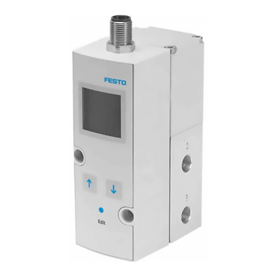
Display and control elements
3
2
4
1
Fig. 4: Display and control elements
1
[Edit] key
2
[UP] key
5
4
4
Compressed air port (1)
5
Exhaust air port (3)
Exhaust air port (3)
1
2
Working air port (2)
3
Compressed air port (1)
3
Display
4
[DOWN] key
1
Advertisement

Subscribe to Our Youtube Channel
Related Manuals for Festo VPPM C1 Series


Summary of Contents for Festo VPPM C1 Series
- Page 1 2021-11f [8110160] 4.2.1 Product design Translation of the original instructions © 2021 all rights reserved to Festo SE & Co. KG Applicable Documents All available documents for the product è www.festo.com/sp. Safety Safety instructions – Only use the product in its original condition without unauthorised modifica- tions.
- Page 2 2. Attach the VPPM -... to the H-rail. Menu Symbol Description level Switching output set, switching output not set Switching output Threshold value comparator Switching point Window comparator Upper switching point SP max Lower switching point SP min SP.O. SetPoint OK Hysteresis Input Lower pressure value...
- Page 3 3. If a shielded electrical connection cable is used, earth the shield at the end of 4. Press and hold the [EDIT] key for 3 seconds. the cable remote from the valve. Ä The VPPM-... is in the RUN mode. 4.
- Page 4 8.3.2 SHOW mode 8.3.3 EDIT mode Not in function (Force) 1) Abhängig von der Ausführung des VPPM-…-C1 2) Dependent on the setting in the "SPEC" menu Fig. 7: EDIT mode The EDIT mode enables the following: In the menu Selection –...
- Page 5 8.4.4 Selecting factory parameter set Switching points ‘SP…’ and hysteresis ‘HY’ 1. In order to activate the EDIT mode, press the [Edit] key. If ‘SP.O.’ is selected Hysteresis Ä The ‘Lock’ display flashes if security blocking is active. 2. Use the [UP] and [DOWN] keys to set the selected security code and confirm Setpoint value with the [Edit] key.
- Page 6 Malfunction Possible cause Remedy Parameter sets recommended for VPPM-12L-... Pressure constant despite Supply pressure P1 too low. Increase supply pressure. Tube length Open system Output volume in ml modified setpoint specification 2000 … 10000 > 10000 0 … 2000 Manual selection of parameter Voltage is applied at digital Apply 0 V DC at digital inputs sets with the [UP] and [DOWN]...
-
Page 7: Control Characteristics
Characteristic electrical values Voltage type VPPM-...-V1...-...C1 Setpoint variable [V DC] 0 … 10 Input resistance (setpoint [kΩ] value) Output actual value load [kΩ] min. 2 Current type VPPM-...-A4...-…C1 Setpoint variable [mA] 4 … 20 Input resistance (setpoint [Ω] value) Output actual value load [Ω] max.
Need help?
Do you have a question about the VPPM C1 Series and is the answer not in the manual?
Questions and answers