
Subscribe to Our Youtube Channel
Related Manuals for Festo CMMS-ST Series


Summary of Contents for Festo CMMS-ST Series
- Page 1 Motor controller Description Mounting and installationTyp CMMS-AS-... Description 564 228 en 0708NH [737 765]...
- Page 3 Edition __________________________________________________ en 0708NH Description _____________________________________ P.BE-CMMS-AS-HW-EN Order No. ___________________________________________________ 564 228 (Festo AG & Co KG., D-73726 Esslingen, 2008) Internet: h ttp://www.festo.com E-mail: service_international@festo.com The copying, distribution and utilization of this document as well as the communication of its contents to others without expressed authorization is prohibited. Offenders will be held liable for the payment of damages.
- Page 4 Index of revisions Author: Name of manual: P.BE-CMMS-AS-HW-EN File name: File location: Consec. no. Description Index of revisions Date of change Creation 0708NH 10.07.2008 Festo P.BE-CMMS-AS-HW-EN en 0708NH...
-
Page 5: Table Of Contents
Incremental encoder interface [X10] ........... 41 3.3.13 Serial parameterization interface RS232 and RS485 – X5 ....41 3.3.14 SD cardholder X12................41 3.3.15 SD memory card ................. 41 Field bus interface ..................... 42 3.4.1 FHPP ....................43 Festo P.BE-CMMS-AS-HW-EN en 0708NH... - Page 6 Interfaces ......................89 Entire CMMS-AS system..................90 Interfaces and plug assignments ............... 92 6.4.1 I/O interface [X1] ................92 6.4.2 Encoder motor – EnDat 2.1 and 2.2 (X2) ..........95 6.4.3 Field bus CAN [X4] ................97 Festo P.BE-CMMS-AS-HW-EN en 0708NH...
- Page 7 Power monitoring for the brake chopper .......... 110 Operating mode and error messages ............... 110 8.2.1 Operating mode and error display ............ 110 8.2.2 Error messages ................111 Technical specifications ..................115 General information ..................115 Festo P.BE-CMMS-AS-HW-EN en 0708NH...
- Page 8 Brake output ..................118 A.3.4 Incremental encoder input [X2] ............118 A.3.5 Incremental sensor interface [X10] ........... 119 A.3.6 RS232/RS485 [X5] ................119 A.3.7 CAN bus [X4]..................119 A.3.8 I/O interface [X1] ................119 Glossary ......................122 Festo P.BE-CMMS-AS-HW-EN en 0708NH...
-
Page 9: General Data
General data Documentation This product manual is intended to help you safely work with the servo motor controller of the CMMS-ST series. It contains safety instructions that have to be observed. This document provides information on: mechanical fitting electrical installation and an overview of the range of functions. -
Page 10: Scope Of Delivery
1. General data Scope of delivery The delivery includes: Number Delivery Motor controller CMMS-AS- C4-3A Operating packet (configuration software, documentation, S7 module, GSD, EDS, firmware) NEKM-C-4 plug assortment Table 1.1 Scope of delivery Festo P.BE-CMMS-AS-HW-EN en 0708NH... -
Page 11: Safety Instructions For Electrical Drives And Controllers
Warning DANGER ! Considerable damage to property and injury to human beings may occur if these instructions are not observed. Warning Dangerous voltage The safety instructions contain reference to dangerous voltages which may occur. Accessories Environment Festo P.BE-CMMS-AS-HW-EN en 0708NH... -
Page 12: General Information
2. Safety instructions for electrical drives and controllers General Information Festo AG & Co.KG is not liable for damage caused by failure to observe the warning in- structions in these operating instructions. Please note Before initial start-up, read through the... -
Page 13: Hazards Due To Improper Use
Hazards due to improper use Warning DANGER ! High electric voltage and high working current! Danger of death or serious bodily injury due to electric shock! Festo P.BE-CMMS-AS-HW-EN en 0708NH... -
Page 14: Safety Instructions
EN standards and VDE/appropriate national regulations, so that they can be disconnected with suitable un- coupling devices (e.g. main switch, fuse, circuit breaker). Warning For switching the control contacts, gold contacts or contacts with high contact pressure should be used. Festo P.BE-CMMS-AS-HW-EN en 0708NH... - Page 15 The following precautionary measures also apply without claim to completeness: VDE 0100 Regulations for setting up high-voltage systems up to 1,000 volts EN 60204-1 Electrical equipment for machines. EN 50178 Equipping high-voltage systems with electronic Festo P.BE-CMMS-AS-HW-EN en 0708NH...
-
Page 16: Safety Instructions For Assembly And Maintenance
Switch the electrical equipment free of voltage via the main switch and make sure that it cannot be switched on again. Wait until the intermediate circuit is discharged after - maintenance work and repairs - cleaning - long periods out of use Festo P.BE-CMMS-AS-HW-EN en 0708NH... -
Page 17: Protection Aganst Touching Electric Components
Protection aganst touching electric components This section concerns only devices and drive components with voltages over 50 V. It is dangerous to touch components with voltages of more than 50 V, as this can cause an Festo P.BE-CMMS-AS-HW-EN en 0708NH... - Page 18 Do not touch the electrical connection points of the components when the device is switched on. Warning Before touching electric components with voltages over 50 V, disconnect the device from the mains or voltage source. Protect the device against being switched on again. Festo P.BE-CMMS-AS-HW-EN en 0708NH...
-
Page 19: Protection By Low Voltage (Pelv) Against Electric Shock
Faults in the measured value and signal generators Faults or non-EMC-compliant components Faults in the software in the higher-order control sys- These faults can occur immediately after the device is switched on or after an uncertain period of operation. Festo P.BE-CMMS-AS-HW-EN en 0708NH... -
Page 20: Protection Aganst Touching Hot Components
If you touch hot parts of the device such as the housing, which con- tains the heat sink and resistors, you may burn yourself. 2.4.7 Protection during handling and installation Handling and assembling certain components in an unsuitable manner can under circum- stances cause injury. Festo P.BE-CMMS-AS-HW-EN en 0708NH... - Page 21 Use lifting devices and tools in a correct manner. If necessary, use suitable protective equipment (e.g. protective glasses, safety shoes, safety gloves). Do not stand under hanging loads. Wipe up spilt liquids on the floor to avoid slipping. Festo P.BE-CMMS-AS-HW-EN en 0708NH...
-
Page 22: Product Description
With a higher-level multiple axis controller, communication can take place via the integrated CAN interface. The parameterisation tool FCT (Festo Configuration tool) makes possible simple opera- tion and start-up of the servo positioning controller. Graphic depictions and pictograms make intuitive parameterization possible. - Page 23 3. Product description DeviceNet Integrated CANopen interface Open interface in accordance with CANopen Festo Profile for Handling and Positioning (FHPP) Protocol in accordance with the CANopen standards DS 301 and DSP 402 Contains "Interpolated position mode" for multiple-axis applications Motion control...
-
Page 24: Interfaces
3. Product description Confiuration Configuration of Motor Controller, Motor and Axis Automatic adjustment of all controller parameters with use of Festo Mechanics 4-channel oscilloscope function English and German Interfaces 3.3.1 Overview of interfaces Setpoint interface / Setpoint specifica- Function Operating mode... -
Page 25: Analogue Setpoint Specification
Mode 1 Jog function Mode 2 Travel program Mode 3 Synchronisation Table 3.2 Mode switching 3.3.3 Analogue setpoint specification The analogue setpoint specification +/- 10VDC can be configured as setpoint specification Speed setpoint value Torque setpoint value Festo P.BE-CMMS-AS-HW-EN en 0708NH... -
Page 26: Rs232 Interface (Diagnosis/ Parameterization Interface)
RS485 specification Baud rate 9600 baud to 115k baud ESD protection ESD protected (16kV) driver Connection Null modem standard, X5 Connection over X5 / DSUB 9 pin / pin Table 3.3 Parameters of the RS232 interface Festo P.BE-CMMS-AS-HW-EN en 0708NH... - Page 27 SAVE! DONE non-volatile flash memory. Setting the baud rate for serial communication BAUD9600 BAUD19200 BAUD38400 BAUD57600 BAUD115200 Unknown command ERROR! Read the version number of the CM (Configuration Man- VERSION? 2300:VERSION:MMMM.SSSS*) agement) release of the firmware Festo P.BE-CMMS-AS-HW-EN en 0708NH...
- Page 28 OW:0061:00000002 OK! or OW:EEEEEEEE enable logic must be set to "DIN5 and RS232". Deactivate end stage. To do this, the controller enable OW:0061:00000003 OK! or OW:EEEEEEEE logic must be set to "DIN5 and RS232". Acknowledge fault OW:0030:00010000 OK! Festo P.BE-CMMS-AS-HW-EN en 0708NH...
- Page 29 Transfer device is ready for use device End device --> Transfer End device displays that the remote Request to send device station should send (send request) Transfer device --> end Transfer device shows reception Clear to send device readiness (send permission) Festo P.BE-CMMS-AS-HW-EN en 0708NH...
- Page 30 RS232. Only the syntax of the commands to read/write the objects is expanded in comparison to the RS232. Syntax: XTnn:HH……HH:CC Meanings: Fixed constants Data (normal command syntax) HH……HH: Node number, identical to the CANopen node number (setting via DIP switch Festo P.BE-CMMS-AS-HW-EN en 0708NH...
- Page 31 The acceleration is thereby written in "acceleration units". That means, they depend on the set CAN factor group. The default setting here is 1 / 2 revolutions/min/s. (24 bit portion before the point, 8 bit portion after the point. =608400:00138800 Acceleration 5000 RPM/s Command: Festo P.BE-CMMS-AS-HW-EN en 0708NH...
-
Page 32: Interfaces For Direct Synchronous Operation
Based on the encoder data, the motor controller generates the tracking signals A, B as well as the zero pulse of an incremental encoder. The number of lines can be set in the FCT with values between 32 … 2048. Festo P.BE-CMMS-AS-HW-EN en 0708NH... - Page 33 Via X1 (digital I/O interface) through selection of mode 3 Please note With setting of synchronization via FCT, the controller only reacts via the synchronisation interface. All other functions of the posi- tioning operating mode are no longer available. Festo P.BE-CMMS-AS-HW-EN en 0708NH...
- Page 34 "Save" button. With a "Reset" (or switching off and back on) of the motor control- ler, the new configuration is activated. To ensure flexibility of the controller, synchronization should be switched on over the I/O interface. Festo P.BE-CMMS-AS-HW-EN en 0708NH...
- Page 35 3. Product description Necessary I/O triggering during synchronisation via I/O mode 3 The connection plan shows the switch position in the active operating state. *) The limit switches are set by default to opener (configuration over FCT) Festo P.BE-CMMS-AS-HW-EN en 0708NH...
- Page 36 3. Product description The connection plan shows the switch position in the active operating state. *) The limit switches are set by default to opener (configuration over FCT) Festo P.BE-CMMS-AS-HW-EN en 0708NH...
- Page 37 The signal MC is set as long as the drive is at a standstill during active synchronisation (DIN8:START set). That is, the MC signal is set as long as the window for "DZ = 0" has not been left. Festo P.BE-CMMS-AS-HW-EN en 0708NH...
-
Page 38: Multi-Firmware Strategy
16 bit / revolution lines incr. encoder Cable length L 25 m Cable design in accordance with Heidenhain specification Limit frequency SCLK 1 MHz Generator supply from the controller, 5 V –0% / +5% = 200 mA max. Festo P.BE-CMMS-AS-HW-EN en 0708NH... -
Page 39: Brake Chopper (Brake Control)
Mode and Stop. (DIN12 and DIN13) (dependent on the parameterized control interface). DOUT0...DOUT3 Digital outputs with 24 V level, DOUT0 is permanently occupied with the function "Ready for operation". Additional outputs can be configured (Target reached, Axis in motion, Target speed achieved..) Festo P.BE-CMMS-AS-HW-EN en 0708NH... - Page 40 Table 6.2 Pin allocation: I/O interface [X1] Mode 0, Table 6.3 Pin allo- cation: I/O interface [X1] Mode 1, Table 6.4 Pin allocation: I/O interface [X1] Mode 2and Table 6.5 Pin allocation: I/O interface [X1] Mode 3. Festo P.BE-CMMS-AS-HW-EN en 0708NH...
-
Page 41: Incremental Encoder Interface [X10]
Via the SD memory card, parameter records can be loaded or firmware can be downloaded. A menu in the configuration software allows you to specify a set of parameters on the memory card, and load it or save it. Festo P.BE-CMMS-AS-HW-EN en 0708NH... -
Page 42: Field Bus Interface
But only one field bus can be active at any given time. For all field busses, the Festo Profile for Handling and Positioning (FHPP) has been imple- mented as the communication protocol. Additionally, for the CAN bus, the communication... -
Page 43: Fhpp
With record selection, the position records stored in the controller are used. In direct operation, the positioning mode, speed control or force control can be employed. These can be dynamically switched over in direct operation as needed. Additional information can be found in the FHPP manual P.BE−CMM−FHPP−SW−EN. Festo P.BE-CMMS-AS-HW-EN en 0708NH... -
Page 44: Can Bus
If the time slot pattern of the position setpoints is greater than the internal position controller cycle time of the controller, the controller automatically interpolates the data values between two prescribed position setpoints. The controller also calculates a corresponding speed pilot control. Festo P.BE-CMMS-AS-HW-EN en 0708NH... -
Page 45: Profibus
The MAC-ID and baud rate are configured over the DIP switches on the front side of the controller. Baud rates up to 500 kBaud are supported. FHPP with the above-described control and operating modes is used as communication protocol. Festo P.BE-CMMS-AS-HW-EN en 0708NH... -
Page 46: Function Overview
Record selection Field bus Direct mode Field bus Record selection Homing run Record selection Field bus Direct mode Field bus Record selection Jog mode Field bus Direct mode Teach-in function via I/O Table 3.15 Operating modes Festo P.BE-CMMS-AS-HW-EN en 0708NH... -
Page 47: Timing Diagram Operation Mode Switchover
The limit switch inputs also affect the ramp generator for the speed set- point. The speed setpoint (without the auxiliary setpoint) is reached via a setpoint ramp. Four acceleration ramps can be parameterized in the range of up to approx. 10 s. The setpoint ramp can be deactivated. Festo P.BE-CMMS-AS-HW-EN en 0708NH... -
Page 48: I²T Function
The parameter records can be called up via: Digital inputs (position record 0 ... 63) RS232 interface (for test purposes only) or a field bus interface Festo P.BE-CMMS-AS-HW-EN en 0708NH... - Page 49 3. Product description Required I/O connection for positioning (mode 0) The connection plan shows the switch position in the active operating state. *) The limit switches are set by default to opener (configuration over FCT) Festo P.BE-CMMS-AS-HW-EN en 0708NH...
-
Page 50: Homing Run
Dec. Hex Dec. Hex Limit switch with zero pulse evaluation Index Impuls Negativer Endschalter Fixed stop with zero pulse evaluation Index Impuls Limit switch Fixed stop Zero pulse Save current position Table 3.16 Homing run methods Festo P.BE-CMMS-AS-HW-EN en 0708NH... - Page 51 If configured: Run at travel speed to axis zero point. Index pulse in a negative direction Run at crawl speed in negative direction to index pulse. This position is saved as a refer- ence point. If configured: Run at travel speed to axis zero point. Festo P.BE-CMMS-AS-HW-EN en 0708NH...
-
Page 52: Timing Diagrams For Homing Run
Limit switch E0 Limit switch E1 DOUT0: READY DOUT1: MC DOUT2: ACK DOUT3: ERROR – =1.6 ms = x ms (dependent on ramps) Fig. 3.4Signal sequence with start of the homing run and with positive design Festo P.BE-CMMS-AS-HW-EN en 0708NH... - Page 53 START Limit switch E0 Limit switch E1 DOUT0: READY DOUT1: MC DOUT2: ACK DOUT3: ERROR Drive is moving =1.6 ms = x ms (dependent on ramps) Fig. 3.5Signal sequence with faulty interruption (contour error, ...) Festo P.BE-CMMS-AS-HW-EN en 0708NH...
-
Page 54: Trajectory Generator
After a start signal is detected, positioning is cancelled and the drive runs at a constant speed. After pre-calculation is completed, the drive runs to the new target position (interrupting). The trajectory generator sends the following messages: Target reached, (Default: digital output DOUT1 - MC) Remaining distance reached. Festo P.BE-CMMS-AS-HW-EN en 0708NH... -
Page 55: I/O Sequence Control
T10 T11 Jog mo- Homing - Conditions Actions of the user RESET / Power ON Time out has expired or the firmware download is com- plete. The initialisation has been carried out successfully. DIN4=1 and DIN5=1 Festo P.BE-CMMS-AS-HW-EN en 0708NH... - Page 56 A fault has occurred which causes the end stage to be switched off Edge controlled fault acknowledgement DIN5: 1 - 0 The error was acknowledged and no other errors are pending. Table 3.18 I/O sequence control Festo P.BE-CMMS-AS-HW-EN en 0708NH...
-
Page 57: Safety Functions, Error Messages
START Holding brake current-carrying Output stage switched on DOUT0: READY DOUT1: MC DOUT2: ACK DOUT3: ERROR Drive is moving =1.6 ms = x ms (dependent on brake ramps) Fig. 3.7 Behaviour when switching off controller enable Festo P.BE-CMMS-AS-HW-EN en 0708NH... - Page 58 Output stage release START Holding brake current-carrying Output stage switched DOUT0: READY DOUT1: MC DOUT2: ACK DOUT3: ERROR Drive is moving =1.6 ms = x ms (dependent on brake ramps) Fig. 3.8Behaviour when switching off end-stage enable Festo P.BE-CMMS-AS-HW-EN en 0708NH...
-
Page 59: Oscilloscope Function
Two channels with 256 16-bit values each can be recorded. Capable of parameterization are: Trigger source (current, speed, position, rotor location, end stage voltage, con- touring error, controller enable, limit switch, positioning started, motion com- Festo P.BE-CMMS-AS-HW-EN en 0708NH... -
Page 60: Jog And Teach Function I/O
"Read from SD after restart" must be inactive, other- wise, when the controller is restarted, the old values will be read off the SD card again. Activating jog/teach function The jog/teach function is started in I/O operation through selection of mode 1. Festo P.BE-CMMS-AS-HW-EN en 0708NH... - Page 61 3. Product description Necessary I/O triggering with jog/teach (mode 1) The connection plan shows the switch position in the active operating state. *) The limit switches are set by default to opener (configuration over FCT) Festo P.BE-CMMS-AS-HW-EN en 0708NH...
- Page 62 3. Product description Settings in the FCT The parameters set here are valid for jogging via I/O interface and jogging via FCT. The acceleration also applies with "single step" over FCT. Festo P.BE-CMMS-AS-HW-EN en 0708NH...
- Page 63 STOP DIN11: Jog - DIN10: Jog + DOUT0: READY DOUT1: MC DOUT2: ACK-TEACH DOUT3: ERROR Drive is moving =1.6 ms = x ms (dependent on brake ramps) Fig. 3.10 Signal sequence with jogging positive and negative Festo P.BE-CMMS-AS-HW-EN en 0708NH...
- Page 64 DOUT1: MC DOUT2: ACK-TEACH DOUT3: ERROR Drive is moving – – – – + – =1.6 ms = x ms (dependent on brake ramps) Fig. 3.11Signal sequence when both signals are activated simultaneously / briefly stag- gered Festo P.BE-CMMS-AS-HW-EN en 0708NH...
-
Page 65: Route Program With Position Record Linking With Switchover Positioning/Torque Control
The route program can be controlled via digital inputs. Digital inputs in which the lev- els (high/low) are evaluated must remain stable for at least 1.6 ms (cycle time of the sequence control for the route program). Festo P.BE-CMMS-AS-HW-EN en 0708NH... - Page 66 Table 3.19 Step criteria for the route program Please note The time specification for STS and TIM is the time entered in the motion profile. The time begins with execution of the position re- cord. Festo P.BE-CMMS-AS-HW-EN en 0708NH...
- Page 67 Position records containing an end speed <> 0 must NOT be used for individual records, since the end speed condition can only be reached in linkages. Activation of set linkage Set linkage is started in I/O operation through selection of mode 2. Festo P.BE-CMMS-AS-HW-EN en 0708NH...
- Page 68 With removal of Din9 "Mode switchover", the ongoing route program is ended. The ongo- ing position record is still run to the end. With removal of Din13 "Stop", the route program is interrupted. The route program must be restarted. Festo P.BE-CMMS-AS-HW-EN en 0708NH...
- Page 69 Applies for positioning records with end speed = 0 Fig. 3.13 Signal sequence at the start of a sequence ENABLE START STOP Positioning record DOUT0: READY DOUT1: MC DOUT2: ACK DOUT3: ERROR Drive is moving =1.6 ms = x ms (dependent on brake ramps) Festo P.BE-CMMS-AS-HW-EN en 0708NH...
-
Page 70: On-The-Fly Measurement
Preset parameter records are provided to the user. For optimal operation of the motor-axis combination, optimization of the control parameters must always be carried out. All drive components and sizes of the entire mechanical construction set are available for the motor series EMMS-AS. Festo P.BE-CMMS-AS-HW-EN en 0708NH... - Page 71 3. Product description EMMS-AS servo motors to be operated at the CMMS-AS: EMMS-AS -40-M, -55-S -TS / -TM / -TSB / -TMB EMMS-AS -70-S, -70-M, -100-S -RS / -RM / -RSB / -RMB Festo P.BE-CMMS-AS-HW-EN en 0708NH...
-
Page 72: Functional Safety Engineering
The safety lead to a loss of the safety function must be checked by the function. machine controller at suitable inter- The loss of the safety func- vals. tion will be detected by the next check. Festo P.BE-CMMS-AS-HW-EN en 0708NH... - Page 73 (main power switch or mains circuit breaker). The EN 60204-1 standard describes three Stop categories that can be used for shutdowns, depending on the results of a risk analysis (see Table 4.3). Festo P.BE-CMMS-AS-HW-EN en 0708NH...
-
Page 74: Integrated "Safe Standstill" Function
Another advantage is the availability of the system. The integrated solution allows the intermediate circuit of the servo controller to remain charged. This means no waiting time when the system is restarted. Festo P.BE-CMMS-AS-HW-EN en 0708NH... - Page 75 1. Switch-off path: End stage enable via [X1] (blocking of the PWM signals; the IGBT drivers no longer receive pulse patterns). Festo P.BE-CMMS-AS-HW-EN en 0708NH...
-
Page 76: Secure Stopping Brake Control
MOSFET that activates the holding brake (brake applied). Caution The user is responsible for the dimensioning and the reliable func- tioning of the holding brake. The functioning of the brake must be ensured via a suitable braking test. Festo P.BE-CMMS-AS-HW-EN en 0708NH... -
Page 77: Functional Method / Timing
Can be set via FCT Fixed (0V) Set speed "n" Both ramps ca be set separately via FCT Seven-segment “H display ” “H” “H” Fig. 4.2 "Safe standstill" timing as per EN 954-1 Category 3 Festo P.BE-CMMS-AS-HW-EN en 0708NH... - Page 78 For motors without a holding brake, this time can be set to 0. 7. At time t7 the drive has reached the set speed. The requires ramp settings can be pa- rameterized using the FCT parameterizing software. Festo P.BE-CMMS-AS-HW-EN en 0708NH...
- Page 79 ([X3], Pin 5 and 6). 6. At time t13, an "H" is displayed on the 7-segment display of the servo controller to indicate a "Safe standstill". This occurs at least 30 ms after the the potential-free feedback contact closes (t13-t12). Festo P.BE-CMMS-AS-HW-EN en 0708NH...
-
Page 80: Application Examples
IGBT end stage driver supply. The drive runs to a standstill and, if present, the motor holding brake is engaged. The drive is in the "Safe standstill" state. The EMERGENCY-STOP switching device is approved for safety category 3 as per EN954-1. Festo P.BE-CMMS-AS-HW-EN en 0708NH... - Page 81 Connection of the motor and the optional holding brake is not shown here and can be found in chapter 6 Electrical installation. Warning DANGER ! The brakes of the system must be designed to be capable of stop- ping the drive motion. Festo P.BE-CMMS-AS-HW-EN en 0708NH...
- Page 82 The request to bring the motor to standstill sets the controller enable to low. The drive slows to a speed of 0 using the defined braking ramp (parameterizable using the Festo Configuration Tool―). After the ramp time has expired (including the switch-off de- Festo P.BE-CMMS-AS-HW-EN en 0708NH...
- Page 83 "End stage driver supply" signals are then switched off after a delay by the safety compo- nent. The switch-off delay must match the braking ramp time (not shown) Warning DANGER ! The brakes of the system must be designed to be capable of stop- ping the drive motion. Festo P.BE-CMMS-AS-HW-EN en 0708NH...
-
Page 84: Mechanical Installation
If the CMMS-AS motor controller is sub- ject to high thermal loads, a mounting clearance (hole interval) - of 70 mm is required! Festo P.BE-CMMS-AS-HW-EN en 0708NH... -
Page 85: Assembly
There are mounting clips at the top and bottom of the CMMS-AS servo positioning control- ler. They are used to attach the motor controller vertically to a control cabinet mounting plate. The clips are part of the radiator profile, ensuring an optimal heat transfer to the control cabinet plate. Festo P.BE-CMMS-AS-HW-EN en 0708NH... - Page 86 5. Mechanical installation Please use size M5 screws to attach the CMMS-AS motor con- troller. Fig. 5.2 Motor controller CMMS-AS: Assembly Festo P.BE-CMMS-AS-HW-EN en 0708NH...
-
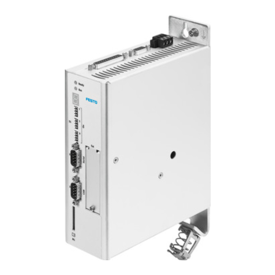
Page 87: Electrical Installation
Electrical installation Device view 1 Status display 2 S1: Field bus settings and boot loader 3 Technology module (optional) 4 M1: SD memory card 5 X4: CAN bus 6 X5: RS232/485 Fig. 6.1 View CMMS-AS Front Festo P.BE-CMMS-AS-HW-EN en 0708NH... - Page 88 2 X9 power supply 3 X10 increment generator output 4 X1 I/O interface Fig. 6.2Top view CMMS-AS 1 X3 safe standstill 2 X2 increment generator input 3 X6 motor connection 4 Screened connection Fig. 6.3Bottom view CMMS-AS Festo P.BE-CMMS-AS-HW-EN en 0708NH...
-
Page 89: Interfaces
If the polarity of the op- erating voltage connections is reversed, or if the operating voltage is too high or the oper- ating voltage and motor connections are reversed, the CMMP-AS servo positioning control- ler will be damaged. Festo P.BE-CMMS-AS-HW-EN en 0708NH... -
Page 90: Entire Cmms-As System
24V power pack for control voltage supply (see Chap- Components ter A.3.1) Power supply (see Chapter A.3.1) Motor controller CMMS-AS Motor EMMS-AS Cable set consisting of motor and encoder line NEBM- A PC with a serial connection cable is required for parameterizing. Festo P.BE-CMMS-AS-HW-EN en 0708NH... - Page 91 6. Electrical installation 1 Main switch 2 Fuse 3 Power pack for control voltage 4 CMMS-AS 5 PC 6 EMMS-AS Fig. 6.4 Complete structure of CMMS-AS with motor and PC Festo P.BE-CMMS-AS-HW-EN en 0708NH...
-
Page 92: Interfaces And Plug Assignments
Sample input (high speed input) DOUT1 24 V 100 mA Output freely programmable – default: Motion complete (high active) DOUT3 24 V 100 mA Output freely programmable – default: Error (low active) AGND Reference potential for the analogue signals Festo P.BE-CMMS-AS-HW-EN en 0708NH... - Page 93 Output freely programmable - default motion complete (high active) DOUT3 24 V 100 mA Output freely programmable - default error (low active) AGND Reference potential for the analogue signals DIN13 Stop input (low active) DIN11 Jog – (high active) Festo P.BE-CMMS-AS-HW-EN en 0708NH...
- Page 94 + 24 V 24 V 100 mA 24 V feed-in feed-out DIN0 Record selection 0 (high active) DIN2 Record selection 2 (high active) DIN4 End stage enable (high active) DIN6 Limit switch 0 DIN8 Start route program Festo P.BE-CMMS-AS-HW-EN en 0708NH...
-
Page 95: Encoder Motor - Endat 2.1 And 2.2 (X2)
Table 6.5 Pin allocation: I/O interface [X1] Mode 3 6.4.2 Encoder motor – EnDat 2.1 and 2.2 (X2) Only encoders with digital EnDat 2.1 or 2.2 interface with a maximum power consumption of 200 mA are supported. Festo P.BE-CMMS-AS-HW-EN en 0708NH... - Page 96 DATA Bidirectional RS485 data cable (differential) Zero impulse transmission with HYPERFACE SCLK Cycle output RS485 (differential) for data transfer via the EnDat interface n.c. n.c. Table 6.6 Pin occupancy encoder motor-EnDat 2.1 and 2.2 (X2) Festo P.BE-CMMS-AS-HW-EN en 0708NH...
-
Page 97: Field Bus Can [X4]
Table 6.8 Pin allocation: RS232/RS485 [X5] 6.4.5 Motor connection [X6] Type on controller Counterplug Plugged/optional plug Material number Combicon 8-pin socket MSTB 2.5/8-ST-5.08 BK Blanking plug kit 547 452 Table 6.9 Plug version: Motor connection [X6] Festo P.BE-CMMS-AS-HW-EN en 0708NH... -
Page 98: Power Supply [X9]
PE connection of the mains power supply +24V / 1A Supply for the control portion with DCDC converter, DOUT0 to DOUT3 and holding brake, max. 1A Common reference potential for the logic power sup- ply and the control section Festo P.BE-CMMS-AS-HW-EN en 0708NH... -
Page 99: Synchronisation Control [X10]
Negative polarity in accordance with RS422 5 V, Ri = 120 Ohm Incremental encoder zero pulse N, negative polarity acc. to RS422 Screen for the connecting cable Table 6.13 Pin allocation: Incremental encoder output / pulse, direction input [X10] Festo P.BE-CMMS-AS-HW-EN en 0708NH... -
Page 100: Sd Card [X12]
Table 6.14 Plug assignments for Safe standstill [X3] 6.4.10 Field bus settings and boot loader Meaning swit- ches Node number Bootloader (If the switch is set to ON, the system searches for new firmware on the SD card) Baud rate Festo P.BE-CMMS-AS-HW-EN en 0708NH... -
Page 101: Instructions On Safe And Emc-Compliant Installation
6.5.1 Explanations and terms Electromagnetic compatibility (EMC) comprises the following requirements: Interference immu- Sufficient interference immunity of an electrical system or electrical nity device against external electrical, magnetic or electromagnetic noise via lines or space. Festo P.BE-CMMS-AS-HW-EN en 0708NH... -
Page 102: Connection Instructions
In order to increase the interference immunity and decrease the interference emission, the CMMS-AS motor controller already has integrated motor chokes and mains filters, which means that it can be operated without additional shielding and filters in most applications. (Up to a max. motor line length of 15m) Festo P.BE-CMMS-AS-HW-EN en 0708NH... -
Page 103: Emc Areas: Second Environment
1. To keep leaked current and losses in the motor connection cable as low as possible, the motor controller CMMS-AS should be placed as close to the motor as possible. 2. The motor and angle encoder cables must be screened. Festo P.BE-CMMS-AS-HW-EN en 0708NH... -
Page 104: Operation With Long Motor Cables
Mains filter. 6.5.7 ESD protection Caution If non-assigned plug connectors are used, there is a danger that damage may occur to the device or to other parts of the system as a result of ESD (electrostatic discharge). Festo P.BE-CMMS-AS-HW-EN en 0708NH... - Page 105 6. Electrical installation Protective caps are available from specialised retailers to prevent such discharges. Festo P.BE-CMMS-AS-HW-EN en 0708NH...
-
Page 106: Preparations For Commissioning
4. Insert the motor cable plug in the corresponding socket on the motor and secure it. 5. Insert the D-sub plug in socket [X2] of the device and secure the locking screws. 6. Check all plug connectors once again. Festo P.BE-CMMS-AS-HW-EN en 0708NH... -
Page 107: Connect The Cmms-As Motor Controller To The Power Supply
You must rectify the cause of the message. If this is the case, see Chapter 8 .2 E rror messagesen (page 1 11). If no display lights 2 3 3 H 2 3 4 H 2 3 5 H up on the device, proceed as follows: Festo P.BE-CMMS-AS-HW-EN en 0708NH... -
Page 108: Timing Diagram Switch-On Sequence Diagram
Can be parameterized (brake parameter run start delay tF < 1.6 ms = N x 0.2 ms Dependent on the fast stop ramp = N x 1.6 ms Can be parameterized (brake parameter switch-off delay tA Fig. 7.1Timing diagram switch-on sequence Festo P.BE-CMMS-AS-HW-EN en 0708NH... -
Page 109: Service Functions And Error Messages
8.1.3 Voltage monitoring for the intermediate circuit Voltage monitoring for the intermediate circuit is triggered as soon as the intermediate circuit voltage leaves the operating voltage range. The power end stage is then deactiva- ted. Festo P.BE-CMMS-AS-HW-EN en 0708NH... -
Page 110: Temperature Monitoring For Motor And Power Section, Temperature Monitoring For The Heat Sink
There is a power monitoring system for the internal braking resistor in the operating soft- ware. Operating mode and error messages 8.2.1 Operating mode and error display A seven-segment display is supported. The display and the meaning of the symbols shown are illustrated in the following table: Festo P.BE-CMMS-AS-HW-EN en 0708NH... -
Page 111: Error Messages
Motor controller and firmware are not compatible Update the firmware. Stack overflow Wrong firmware? Reload standard firmware if necessary. Contact Technical Support. Undervoltage in intermediate Undervoltage monitoring is configured using the FCT. circuit Measure intermediate circuit voltage. Check configuration. Festo P.BE-CMMS-AS-HW-EN en 0708NH... - Page 112 The signals are interrupted when messages are sent. while sending Motor identification fault Initialization fault Please contact Technical Support. Unexpected status Contour error limit value ex- Increase error window. ceeded Acceleration parameter too large. Pulse wheel angle monitoring Festo P.BE-CMMS-AS-HW-EN en 0708NH...
- Page 113 Route program: Jump target Jump to a line outside permitted range error Positioning: Error in pre- The positioning target cannot be reached through the calculation positioning or edge conditon options. Check parame- ters of the position records in question. Festo P.BE-CMMS-AS-HW-EN en 0708NH...
- Page 114 Fault messages can be acknowledged with: the parameterizing interface, via the field bus (control word), a falling edge at DIN5 (controller enable). Please note Safety devices must be regularly checked according to the characteristics of the system. Festo P.BE-CMMS-AS-HW-EN en 0708NH...
-
Page 115: Technical Specifications
Second environment l 15m (Industrial) Cable capacitance of one phase against screen or between two lines C‘ 220pF/m Table A.3 Technical data: Cable data Sensors Values Digital sensor N/C contact: < 1 k > 10 k cold Festo P.BE-CMMS-AS-HW-EN en 0708NH... -
Page 116: Operation And Display Components
Control elements The node number can be set via DIP switches on the front of the device: 7x node number 1x load firmware from SD card 2x baud rate 1X CAN on / off 1x terminating resistor Festo P.BE-CMMS-AS-HW-EN en 0708NH... -
Page 117: Interfaces
To release the holding brake, the voltage tolerances at the holding brake connection terminals must be maintained. Features Values Internal braking resistor Pulse power 700 W Rated output 15 W Response threshold 390 V Hysteresis 10 V Table A.7 Technical data: Internal braking resistor [X9] Festo P.BE-CMMS-AS-HW-EN en 0708NH... -
Page 118: Motor Connection [X6] Cmms-As
5 V differential / RS422 / RS485 Angle resolution / Number of lines incr. encoder Controller-internal up to 16 bit / revolution L 25m Cable length Cable design in accordance with Heidenhain specifi- cation Limit frequency SCLK 1 MHz Festo P.BE-CMMS-AS-HW-EN en 0708NH... -
Page 119: Incremental Sensor Interface [X10]
Values Protocol CANopen DS301, DSP402 and FHPP Baud rate Max. 1 MBaud Terminating resistor 120 Ω (can be activated via DIP switches) Table A.13 Technical data: CAN bus [X4] A.3.8 I/O interface [X1] Digital inputs Values Festo P.BE-CMMS-AS-HW-EN en 0708NH... - Page 120 Table A.16 Technical data: Analogue inputs Analogue outputs Values Signal level 0 … 10 V Version Single-ended against AGND Resolution 9 bit Output reaction time < 250 µs Protective function Short circuit against AGND Table A.17 Technical data: Analogue outputs Festo P.BE-CMMS-AS-HW-EN en 0708NH...
- Page 121 A. Technical specifications Festo P.BE-CMMS-AS-HW-EN en 0708NH...
-
Page 122: Glossary
Interference emissi- Sufficiently low interference emission of electrical, magnetic or elec- tromagnetic interference of an electrical system or an electrical de- vice on other devices in the environment via lines and space. Festo P.BE-CMMS-AS-HW-EN en 0708NH... - Page 123 Homing run.......... 50 Interpolated position mode ....44 Notes General information ......12 Security ..........11 Symbols ........... 11 Positioning controller ......48 Safety instructions ......11, 14 Scope of delivery ......... 10 Setpoint selectors ....... 47 Festo P.BE-CMMS-AS-HW-EN en 0708NH...
Need help?
Do you have a question about the CMMS-ST Series and is the answer not in the manual?
Questions and answers