Table of Contents
Advertisement
Quick Links
Notice to End Users
This User's Guide & Technical Reference is for assisting system
manufacturers and end-users in setting up and installing the mainboard.
Every effort has been made to ensure that the information in this manual is
accurate. Soltek Computer Inc. is not responsible for printing or clerical
errors. Information in this document is subject to change without notice
and does not represent a commitment on the part of Soltek Computer
Inc.
No part of this manual may be reproduced, transmitted, translated into any
language in any form or by any means, electronic or mechanical, including
photocopying and recording, for any purpose without the express written
permission of Soltek Computer Inc.
Companies and products mentioned in this manual are for identification
purposes only. Product names appearing in this manual may or may not be
registered trademarks or copyrights of their respective companies.
SOLTEK COMPUTER INC. PROVIDES THIS MANUAL "AS IS" WITHOUT
WARRANTY OF ANY KIND, EITHER EXPRESS OR IMPLIED, INCLUDING
BUT NOT LIMITED TO THE IMPLIED WARRANTIES OR CONDITIONS OF
MERCHANTABILITY OR FITNESS FOR A PARTICULAR PURPOSE. IN NO
EVENT SHALL SOLTEK COMPUTER INC. BE LIABLE FOR ANY LOSS OR
PROFITS, LOSS OF BUSINESS, LOSS OF USE OR DATA, INTERRUPTION OF
BUSINESS, OR FOR INDIRECT, SPECIAL, INCIDENTAL, OR
CONSEQUENTIAL DAMAGES OF ANY KIND, EVEN IF SOLTEK COMPUTER
INC. HAS BEEN ADVISED OF THE POSSIBILITY OF SUCH DAMAGES
ARISING FROM ANY DEFECT OR ERROR IN THIS MANUAL OR PRODUCT.
(C) Copyright 1999 Soltek Computer Inc. All right reserved
Web site: http://www.soltek.com.tw
Email:
support@soltek.com.tw
Edition: August 1999
Version: 1.0
SL-63AV SERIALS
i
Advertisement
Table of Contents

Related Manuals for SOLTEK SL-63AV


Summary of Contents for SOLTEK SL-63AV
- Page 1 Soltek Computer Inc. is not responsible for printing or clerical errors. Information in this document is subject to change without notice and does not represent a commitment on the part of Soltek Computer Inc. No part of this manual may be reproduced, transmitted, translated into any...
-
Page 3: Table Of Contents
Contents Chapter 1: Introduction ----------------------------------------1 Features -----------------------------------------------------------------------------1 CPU ---------------------------------------------------------------------------1 Chipset ------------------------------------------------------------------------1 L2 Cache ----------------------------------------------------------------------1 Main Memory ----------------------------------------------------------------1 BIOS---------------------------------------------------------------------------2 Super I/O Function ----------------------------------------------------------2 Other Functions --------------------------------------------------------------2 Mainboard Layout with Default Settings ---------------------------------------3 Chapter 2: Hardware Setup -----------------------------------4 JBAT1: Clear CMOS Data --------------------------------------------------------10 Connectors------------------------------------------------------------------------11 KB1:Keyboard Connector -------------------------------------------------------- 11 MS1:PS/2 Mouse Connector ----------------------------------------------------- 11... - Page 4 J2 Switch Signal Summary----------------------------------------16 Chapter 3: BIOS Setup --------------------------------------17 Standard CMOS Setup ---------------------------------------------------------- 19 BIOS Features Setup ------------------------------------------------------------ 21 Chipset Features Setup --------------------------------------------------------- 27 Power Management Setup ----------------------------------------------------- 31 PnP/PCI Configuration Setup -------------------------------------------------- 35 Load Setup Defaults ------------------------------------------------------------ 38 CPU Speed Setting ------------------------------------------------------------ 39 Integrated Peripherals ----------------------------------------------------------- 40 Supervisor/User Password------------------------------------------------------ 43 IDE HDD Auto Detection ------------------------------------------------------ 45...
-
Page 5: Chapter 1: Introduction
Chapter 1 Introduction Features 1. Supports Intel PPGA Celeron 370 CPU and other compatible CPUs using Socket 370 at 300A ~ 533 MHz or higher 2. Supports CPU voltage auto detect circuit 3. Supports 66/100/112 MHz Bus Clock. Chipset 1. VIA 693 chipset 2. -
Page 6: Bios
BIOS 1. AWARD Plug and Play BIOS 2. Supports ACPI Function 3. Flash Memory for easy upgrade Super I/O Function 1. Integrated USB (Universal Serial Bus) controller with two USB ports. 2. Supports 2 IDE channels with 4IDE devices (including ZIP/LS-120 devices) 3. -
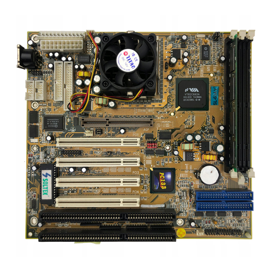
Page 7: Mainboard Layout With Default Settings
Mainboard Layout with Default Settings The default settings of the following figure is for the PPGA Celeron 370- 300A MHz with the Jumperless function Enabled. COM1 JWOL1 COM2 Flash BIOS LPT1 FDD1 SFAN1 CFAN1 Socket 370 JP13 JP14 JP15 596B JP16 Chipset PFAN1... -
Page 8: Chapter 2: Hardware Setup
Chapter 2 Hardware Setup There are two ways to set the CPU type and both ways are controlled by JP13, JP14, JP15, and JP16: 1. Use jumpers (hardware): JP13 ~ JP16 must be set. Refer to the following pages (CPU Type Jumper Configuration). 2. -
Page 9: I D E L A C T I V I T Y L I G H T : ( J 2 P I
Celeron 433 (66MHz x 6.5X) Celeron 466 (66MHz x 7.0X) Celeron 500 (66MHz x 7.5X) Celeron 533 (66MHz x 8.0X) System Memory Configuration This VIA 693 motherboard supports 168 pin DIMM of 4MB, 8MB, 16MB, 32MB, 64MB, 128MB and 256MB to form a memory size between 8MB to 768MB (SDRAM). - Page 10 CPU Heat Sink Installation Follow the following steps in order to install your Intel PPGA Celeron 370 properly. Step 1: If you use INTEL BOX TYPE Celeron 370CPU and the clip block the case hen you must change the clip with the one that we send you within the mainboard Block case Step 2:...
- Page 11 Put the fan back on the heat sink firmly Jumper Settings XFAN 1: Onboard FAN (12V) Connector XFAN1 Function XFAN Function CFAN1 CPU FAN PFAN1 Power FAN SFAN1 Chassis FAN...
- Page 12 JP13 ~ JP16: Bus Ratio Select Bus Ratio JP13 ~ JP16 Bus Ratio JP13 ~ JP16 2.0x 2.5x 3.0x 3.5x 4.0x 4.5x 5.0x 5.5x 6.0x 6.5x 7.0x 7.5x By BIOS 8.0 x (jumperless setting) (default)
- Page 13 JP3, JP4: Bus Clock Select Bus Clock JP3, JP4 66MHz 100MHz Auto detect 66/100MHz (default) JP11, JP12: USB Port Select USB Port JP11,JP12 Redirect USB port 1 To AGP Redirect USB port 1 To USB connector(default)
-
Page 14: Jbat1: Clear Cmos Data
JVGA1: VGA Card This jumper is set for the PCI VGA card only. Open this jumper when the system isn’t able to boot up. If you use AGP card, it is important to set default with JVGA1 JVGA1 For Special PCI VGA Card* Normal (default) -
Page 15: Connectors
Connectors KB1: Keyboard Connector A 5-pin female DIN keyboard connector is located at the upper right corner of the motherboard. Plug the keyboard jack directly to this connector. MS1:PS/2 Mouse Connector Attach PS/2 mouse cable to this 6-pin connector. LPT:Parallel Port The system provides a 2x13-pin parallel port connector, PRT. -
Page 16: Power Connector
Power Connector The power connector has two types: AT and ATX Plug the AT dual connectors from the power directly onto the board connector while making sure the black leads are in the center. AT POWER CONNECTOR... -
Page 17: F D C : F L O P P Y D R I V E C O N N E C T O
FDC:Floppy Drive CONNECTOR The system board has a 2x17-pin floppy drive connector, FDC. Connect one end of a floppy drive cable to this connector and the other end to a floppy drive. IDE1/IDE2: Primary/Secondary IDE Connectors The system board has a 32-bit ENHANCED PCI IDE Controller that provides for HDD connectors, IDE1 (primary) and IDE2 (secondary). -
Page 18: Speaker Connector(J3 Pin1-4)
Speaker Connector (J3 pin1-4) The speaker connector is a 4-pin connector for connecting the system to the case. (See the following drawing for jumper position.) Reset Switch (J3 pin5, 6) The system board has a 2-pin connector for rebooting your computer without having to turn off your power switch. -
Page 19: J2 In12,13: Pwr Switch
USB1: USB Connector D0+ Vcc D0- GND Turbo LED (J2 pin14, 15) Connect the case’s turbo LED to this connector. J2 and J3 • : HDD LED ‚ : INFRARED (IR) ƒ : POWER SWITCH „ : SMI … : SPEAKER †... -
Page 20: J2 Switch Signal Summary
J2 Switch Signal Summary Signal Description HDD LED Signal HDD LED Connector HDD LED Signal N.C. No Connection Infrared Transmit Signal Infrared Receive Signal Infrared Connector (low speed) Infrared Receive Signal (high speed) N.C. No Connection 5V Standby Power Switch(for ATX Power) SMI Signal J3 Switch Signal Summary Signal Description... -
Page 21: Chapter 3: Bios Setup
Chapter 3 AWARD BIOS SETUP This 693 Apollo Pro-Plus motherboard comes with the AWARD BIOS from AWARD Software Inc. Enter the Award BIOS program Main Menu by: 1. Turn on or reboot the system. After a series of diagnostic checks, the following message will appear: PRESS <DEL>... - Page 22 3. Using the arrows on your keyboard, select an option, and press <Enter>. Modify the system parameters to reflect the options installed in your system. 4. You may return to the Main Menu anytime by pressing <ESC> . 5. In the Main Menu, “SAVE AND EXIT SETUP” saves your changes and reboots the system, and “EXIT WITHOUT SAVING”...
-
Page 23: Standard Cmos Setup
Standard CMOS Setup Standard CMOS Setup allows you to record some basic system hardware configuration and set the system clock and error handling. You only need to modify the configuration values of this option when you change your system hardware configuration or the configuration stored in the CMOS memory gets lost or damaged. - Page 24 A short description of the screen options is as follows: Date (mm:dd:yy) Set the current date and time. Time (hh:mm:ss) Primary This field records the specifications (Secondary) for all non-SCSI hard disk drives Master/Slave installed in your system. Refer to the respective documentation on how to install the drives.
-
Page 25: Bios Features Setup
BIOS Features Setup BIOS Features Setup allows you to improve your system performance or set up system features according to your preference. Run the BIOS Features Setup as follows: 1. Choose “BIOS FEATURES SETUP” from the Main Menu and a screen with a list of options will appear. ROM PCI/ISA BIOS BIOS FEATURES SETUP AWARD SOFTWARE, INC. - Page 26 <F6>: Load all options with the BIOS default values. <F7>: Load all options with the Setup default values.
- Page 27 A short description of screen options follows: Virus Warning Enabled: Activates automatically when the system boots up causing a warning message to appear if there is anything attempting to access the boot sector or hard disk partition table. Disabled: No warning message will appear when there is something attempting to access the boot sector or...
- Page 28 Boot Sequence Default is “A, C, SCSI” This option determines which drive to look at first for an operating system. Swap Floppy Drive Choose Enabled or Disabled (default). This option swaps floppy drive assignments when it is enabled. Boot Up Floppy Enabled (default): During POST, Seek BIOS checks the track number of the...
- Page 29 Typematic Rate Choose Enabled or Disabled Setting (default). Enable this option to adjust the keystroke repeat rate. Typematic Rate Range between 6 (default) and 30 (Chars/Sec) characters per second. This option controls the speed of repeating keystrokes. Typematic Delay Choose 250 (default), 500, 750, and (Msec) 1000.
- Page 30 C8000-CBFFF to These options are used to shadow DC000-DFFF other expansion card ROMs. Shadow 3. Press <ESC> and follow the screen instructions to save or disregard your settings.
-
Page 31: Chipset Features Setup
Chipset Features Setup Chipset Features Setup changes the values of the chipset registers. These registers control the system options. Run the Chipset Features Setup as follows: 1. Choose “CHIPSET FEATURES SETUP” from the Main Menu and a screen with a list of options will appear. ROM PCI/ISA BIOS(2A6LGSNC) CHIPSET FEATURES SETUP AWARD SOFTWARE, INC. - Page 32 A short description of screen options follows: Bank 0/1 2/3 4/5 This item allows you to select the value in DRAM Timing this field, depending on whether the board has paged DRAMs or EDO (extended data output) DRAMs. The Choice: EDO 50ns, EDO 60ns,Slow, Medium, Fast, Turbo.
- Page 33 Concurrent When disabled, CPU bus will be occupied PCI/HOST during the entire PCI operation period. The Choice: Enabled, Disabled System BIOS Choose Enabled or Disabled Cacheable (default). When Enabled, the access to the system BIOS ROM addressed at F0000H-FFFFFH is cached. Video RAM Choose Enabled or Disabled Cacheable...
- Page 34 USB Keyboard Enabled: Enables function when Support the USB keyboard is being used. Disabled: (default) When the AT keyboard is being used. OnChip Sound Enabled (default):Turn on AC97 chip Controller Disabled: Turn off AC97 chip controller or User can external add-on sound card OnChip Modem Enabled :Turn on MC99 feature Disabled(default):Disabled...
-
Page 35: Power Management Setup
Power Management Setup Power Management Setup sets the system’s power saving functions. 1. Choose “POWER MANAGEMENT SETUP” from the Main Menu and a screen with a list of options will appear. ROM PCI/ISA BIOS(2A6LGSNC) POWER MANAGEMENT SETUP AWARD SOFTWARE, INC. ACPI Function :Disabled Primary INTR... - Page 36 A short description of screen options follows: ACPI Function Enabled: Turn on ACPI Function Disabled(default):Turn off ACPI Function Power Choose Max. Saving, User Define Management (default), Disabled, or Min. Saving. PM Control by Choose Yes (default) or No. You need to choose Yes when the operating system has the APM functions, otherwise choose No.
- Page 37 power 4 seconds after pushing the power button (to meet PC97/98 spec.) Doze Mode This mode sets the CPU speed down to 33MHz. Standby Mode These two options allow you to Suspend Mode choose the mode for the different timers. The Standby Mode turns off the VGA monitor, and the Suspend Mode turns off the CPU and saves the energy of the system.
- Page 38 IRQ (#), NMI; Enabled: (default) The system can not enter the power Primary IDE 0 saving mode when I/O Primary IDE 1; ports or IRQ # is Secondary IDE 0 activated Secondary IDE 1; Disabled: The system still can enter the power saving mode Floppy Disk;...
-
Page 39: Pnp/Pci Configuration Setup
PnP/PCI Configuration Setup PnP/PCI Configuration Setup configures the PCI bus slots. Run the Chipset Features Setup as follows: 1. Choose “PnP/PCI CONFIGURATION SETUP” from the Main Menu and a screen with a list of options will appear. ROM PCI/ISA BIOS(2A6LGSNC) PNP/PCI CONFIGURATION AWARD SOFTWARE, INC. - Page 40 A short description of screen options follows: PNP OS Installed Yes: OS supports Plug and Play function. No (default): OS doesn’t support Plug and Play function. Note: BIOS will automatically disable all PnP resources except the boot device card when you select Yes on Non-PnP OS.
- Page 41 other devices but the USB controller will still not be disabled (only IRQ was removed.) Assign IRQ for Choose Enabled (default) or Disabled. Enabled: Add one IRQ to VGA controller. Disabled: Remove IRQ from VGA controller. The system will have extra IRQ for other devices but the VGA controller will still not be disabled (only IRQ will be removed.)
-
Page 42: Load Setup Defaults
Load Setup Defaults Load Setup Defaults option loads the default system values to the system configuration fields. If the CMOS is corrupted the defaults are loaded automatically. Choose this option and the following message will appear: “Load Setup Defaults (Y/N)? N” To use the Setup defaults, change the prompt to “Y”... -
Page 43: Cpu Speed Setting
CPU SPEED SETTING ROM PCI/ISA BIOS(2A6LGSNC) PNP/PCI CONFIGURATION AWARD SOFTWARE, INC. Current cpu Temp. :33 C / 91 F Current System Temp. :26 C / 78 F Current CPUFAN1 Speed : 3810 RPM Current CPUFAN2 Speed 0 RPM Vcore: 1.96V 2.5V 2.46 V 3.3V:... -
Page 44: Integrated Peripherals
Integrated Peripherals Integrated Peripherals option changes the values of the chipset registers. These registers control system options in the computer. 1. Choose “INTEGRATED PERIPHERALS” from the Main Menu and a screen with a list of options will appear. ROM PCI/ISA BIOS(2A6LGSNC) INTEGRATED PERIPHERALS AWARD SOFTWARE, INC. - Page 45 A short description of screen options is as follows: IDE Primary Choose Auto (default) or Mode 0~4. Master/Slave PIO The BIOS will detect the HDD Mode IDE Secondary type automatically when you Master/Slave PIO choose Auto. You need to set to a lower mode than Auto when your hard disk becomes unstable.
- Page 46 IR Function Choose Half or Full Duplex Onboard Parallel Choose the printer I/O address: Port 378H/IRQ7 (default), 3BCH/IRQ7, 278H/IRQ5, Disabled Onboard Parallel Choose Normal (default), ECP/EPP Mode EPP, or ECP mode. The mode depends on the external device connected to this port. ECP Mode Use Choose DMA3 (default) or DMA1.
-
Page 47: Supervisor/User Password
Supervisor/User Password These two options allow you to set your system passwords. Normally, the supervisor has a higher ability to change the CMOS setup option than the user. The way to set up the passwords for both Supervisor and User are as follows: 1. - Page 48 you did, otherwise the old password will still be there the next time you turn your machine on. 8. Press <ESC> to exit to the Main Menu. Note: If you forget or lose the password, the only way to access the system is to clear the CMOS RAM by setting JBAT1.
-
Page 49: Ide Hdd Auto Detection
IDE HDD Auto Detection IDE HDD Auto Detection detects the parameters of an IDE hard disk drive and automatically enters them to the Standard CMOS Setup screen. The screen will ask you to select a specific hard disk for Primary Master after you select this option. -
Page 50: Save & Exit Setup
Save & Exit Setup Save & Exit Setup allows you to save all modifications you have specified into the CMOS memory. Highlight this option on the Main Menu and the following message appears: SAVE to CMOS and EXIT (Y/N)? Y Press <Enter>... -
Page 51: Exit Without Saving
Exit Without Saving Exit Without Saving allows you to exit the Setup utility without saving the modifications that you have specified. Highlight this option on the Main Menu and the following message appears: Quit Without Saving (Y/N)? N You may change the prompt to “Y” and press the <Enter> key to leave this option. -
Page 52: Appendix 1: Driver Installation
Appendix 1---Driver Installation Flash Memory Update Installation 1. Download BIOS files and flash utility from your board vendor. They are: awdflash.exe and .bin file. 2. Copy them to bootable diskette and boot from diskette. 3. The diskette does not include memory manager e.g. emm386.exe,qemm and himem.sys 4. - Page 53 VIA PCI IRQ Routing Miniport for Windows 9x Installation Windows95/Windows98: 1. Go to the CD-ROM disk, we suggest the CD-ROM title is D:\. 2. Find and run D:\Patch\Via\Virq9x\Setup.exe Note: Before install Windows98, user must enable two functions for this miniport driver in the BIOS menu, one is “OnChip USB”...
Need help?
Do you have a question about the SL-63AV and is the answer not in the manual?
Questions and answers