Table of Contents
Advertisement
Available languages
Available languages
TABLE OF CONTENTS
****************
General Safety Rules .......................2-3
Specific Safety Rules ......................... 3
Symbols ..............................................4
Electrical ..........................................5-6
Features ...........................................7-8
Tools Needed ..................................... 8
Loose Parts ...................................9-10
Assembly .....................................11-23
Operation .....................................24-30
Adjustments ................................31-34
Maintenance ................................35-36
Warranty ...........................................37
Parts Ordering/Service ....... Back Page
WARNING:
To reduce the risk of injury, the
user must read and understand
the operator's manual before us-
ing this product.
SAVE THIS MANUAL FOR
FUTURE REFERENCE
TABLE DES MATIÈRES
****************
Règles de sécurité générales ..........2-3
Règles de sécurité particulières ......... 4
Symboles ............................................5
Caractéristiques électriques ............6-7
Caractéristiques ..............................8-9
Outils nécessaires .............................. 9
Pièces détachées ........................10-11
Assemblage .................................12-19
Utilisation .....................................20-26
Réglages ......................................27-29
Entretien ......................................30-31
Garantie ............................................32
Commande de pièces /
réparation ..........................Page arrière
AVERTISSEMENT :
Pour réduire les risques de blessures,
l'utilisateur doit lire et veiller à bien
comprendre le manuel d'utilisation
avant d'utiliser ce produit.
CONSERVER CE MANUEL
POUR FUTURE RÉFÉRENCE
OPERATOR'S MANUAL
MANUEL D'UTILISATION
MANUAL DEL OPERADOR
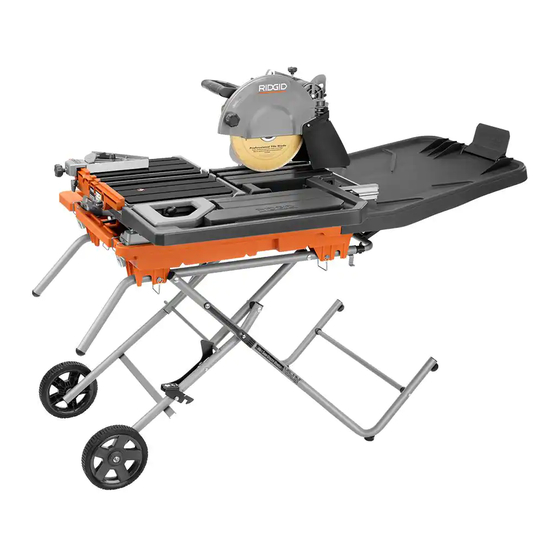
10 in. TILE SAW
SCIE À CARREAUX
DE 254 mm (10 po)
SIERRA DE LOSAS
DE 254 mm (10 pulg.)
To register your RIDGID
register.ridgidpower.com
register.ridgidpower.com
Para registrar su producto
de RIDGID, por favor visita:
register.ridgidpower.com
ÍNDICE DE CONTENIDO
Reglas de seguridad generales .......2-3
Reglas de seguridad especificas ....... 4
Símbolos ............................................5
Aspectos eléctricos .........................6-7
Características ................................8-9
Herramientas necesarias .................. 10
Piezas sueltas ..............................10-11
Armado ........................................12-19
Funcionamiento ...........................20-26
Ajustes .........................................27-29
Mantenimiento .............................30-31
Garantía ............................................32
Pedidos de piezas/
servicio .......................... Pág. posterior
ADVERTENCIA:
Para reducir el riesgo de lesiones, el
usuario debe leer y comprender el
manual del operador antes de usar
este producto.
GUARDE ESTE MANUAL
PARA FUTURAS CONSULTAS
R4093
product, please visit:
Pour enregistrer votre
produit de RIDGID,
s'il vous plaît la visite:
****************
Advertisement
Table of Contents

Related Manuals for RIDGID R4093


Summary of Contents for RIDGID R4093
-
Page 1: Table Of Contents
To register your RIDGID product, please visit: register.ridgidpower.com Pour enregistrer votre produit de RIDGID, s’il vous plaît la visite: register.ridgidpower.com Para registrar su producto de RIDGID, por favor visita: register.ridgidpower.com TABLE OF CONTENTS TABLE DES MATIÈRES ÍNDICE DE CONTENIDO **************** **************** **************** ... -
Page 2: General Safety Rules
GENERAL SAFETY RULES SECURE WORK. Use clamps or a vise to hold work when practical, it is safer than using your hand and frees both WARNING: hands to operate the tool. Read and understand all instructions. Failure to DON’T OVERREACH. Keep proper footing and balance follow all instructions listed below, may result in at all times. -
Page 3: Specific Safety Rules
GENERAL SAFETY RULES INSPECT TOOL CORDS PERIODICALLY. If damaged, STAY ALERT AND EXERCISE CONTROL. Watch what have repaired by a qualified service technician at an you are doing and use common sense. Do not operate authorized service facility. The conductor with insulation tool when you are tired. -
Page 4: Symbols
SYMBOLS The following signal words and meanings are intended to explain the levels of risk associated with this product. SYMBOL SIGNAL MEANING Indicates a hazardous situation, which, if not avoided, will result in death or DANGER: serious injury. Indicates a hazardous situation, which, if not avoided, could result in death or WARNING: serious injury. -
Page 5: Electrical
ELECTRICAL EXTENSION CORDS ELECTRICAL CONNECTION Use only 3-wire extension cords that have 3-prong ground- This tool is powered by a precision built electric motor. It ing plugs and 3-pole receptacles that accept the tool’s plug. should be connected to a power supply that is 120 V, AC only (normal household current), 60 Hz. - Page 6 ELECTRICAL If the saw is used with an extension cord, ensure the con- nection of the tool’s power cord and the extension cord are not on the ground. If a protected outlet is not available, do not use the saw until an outlet can be changed or auxiliary protection can be obtained.
-
Page 7: Features
FEATURES PRODUCT SPECIFICATIONS Wheel diameter ............10 in. Diagonal capacity (tile size) ........24 in. Wheel arbor .............. 5/8 in. Maximum depth of cut .......... 3-1/2 in. Throat capacity ............18 in. Rating ...........120 V~, 15 Amps, 60 Hz Rip capacity (tile size) ..........36 in. No-load speed ........4,000 r/min. -
Page 8: Tools Needed
FEATURES KNOW YOUR TILE SAW MICRO-CUT FENCE SUPPORT - This machined ledge helps prevent tile from cracking. See Figure 4. MITER GUIDE - The easy-to-read indicator on the miter The safe use of this product requires an understanding of guide shows the exact angle for a miter cut with detents at the information on the tool and in this operator’s manual as 0°, 22.5°, and 45°. -
Page 9: Loose Parts
LOOSE PARTS The following items are included with your tile saw: Fig. 6 A - Left outer tube ............. 1 I - Wheel ................2 J - Spacer (large) ............... 2 B - Right outer tube ............1 C - Lower brace ..............1 K - Carriage bolt .............. - Page 10 LOOSE PARTS The following items are included with your tile saw: Fig. 7 A - Motor head assembly ..........1 J - Frame and sliding table ..........1 B - Tile cutting wheel ............1 K - Sliding table extension ..........1 C - Rear splash guard ............1 L - Rear water tray extension .........1 D - Side splash guard .............1 M - Side water tray extension .........1...
-
Page 11: Assembly
ASSEMBLY UNPACKING INSTALLING MOTOR HEAD ASSEMBLY TO See Figures 6 - 7. BASE See Figure 8. This product requires assembly. Align the holes in the motor head assembly with the holes Carefully lift the parts from the carton and place on a level on the base. - Page 12 ASSEMBLY ASSEMBLING WSUV STAND CENTER See Figures 9 - 15. BRACE SMALL SPACERS WARNING: STOP To avoid serious personal injury, always make sure the tile saw is securely mounted to a workbench CARRIAGE or an approved leg stand. NEVER operate the saw RELEASE BOLT on the floor.
- Page 13 ASSEMBLY Place a large spacer over the end of the lower brace. Slide a large washer, wheel, and small washer onto an axle. Secure in place using nut. Repeat with the second Insert a hex bolt through the bottom of the right outer wheel.
- Page 14 WSUV stand’s handles. NOTE: The portion of the water tray with the Ridgid logo should be on the wheel side of the stand. Secure the water tray to the stand using four hitch pins.
- Page 15 ASSEMBLY INSTALLING MOTOR HEAD AND BASE TO Tilt the base and insert heavy duty tab into the bar slot on water tray. WATER TRAY Secure the base in place with latches on front of the water See Figure 20. tray.
- Page 16 ASSEMBLY INSTALLING/REMOVING THE FRAME AND To lock the frame: SLIDING TABLE Pull the frame lock lever out and turn 90˚ clockwise to the “locked position”. See Figures 21 - 23. Release the lever. Pull the frame lock lever out and turn 90˚ counterclockwise to the “unlocked position”.
- Page 17 ASSEMBLY TILE CUTTING WHEEL For maximum performance and safety, it is recommended that you use the 10 in. cutting wheel provided with your saw. Additional cutting wheels of the same high quality are available at your local dealer. SPINDLE LOCK WARNING: WHEEL Do not use cutting wheels rated less than the no-...
- Page 18 ASSEMBLY SCREW HOLE WARNING: If the inner washer has been removed, replace it before placing wheel on spindle. Failure to do so WASHER could cause an accident since the wheel will not tighten properly. Never use wheels that have open- ings, grooves, or teeth on this tool.
- Page 19 ASSEMBLY WATER TRAY INSTALLING THE REAR WATER TRAY FRAME EXTENSION SLOT See Figure 29. Standing at the back of the saw, hold the rear water tray extension with the tray tabs pointing toward the slots in the water tray. Tilt the tray up and slide the tray tabs into the slots.
- Page 20 ASSEMBLY SLOTS INSTALLING SIDE WATER TRAY EXTENSION See Figure 31. From the right side of the saw, slide the second (or side) water tray extension into the slots on the frame and sliding table extension. ADJUSTING THE DROP FENCE See Figure 32. The drop fence can be lowered when using the rip fence or raised to accommodate the miter guide.
- Page 21 ASSEMBLY INSTALLING THE MITER GUIDE MITER GUIDE MITER KNOB See Figure 34. GUIDE The miter guide can be used from both the left and right side of the cutting wheel. LOCK NOTE: The drop fence must be locked in its raised position KNOB when using the miter guide.
- Page 22 ASSEMBLY LOCK PIN TO CLOSE/OPEN THE WSUV STAND See Figures 36 - 38. NOTE: Be sure the frame is secured to the latches before closing. Lock sliding table and frame. Remove water tray extensions and any workpieces from LOCK KNOB the tool.
- Page 23 ASSEMBLY To open the WSUV stand: Step on the release lever and pull the grips toward you at the same time. Once the WSUV stand is released from the release lever, ease the WSUV stand toward the floor by pushing the grips toward the floor.
-
Page 24: Operation
OPERATION PUMP ON WARNING: WITH Do not allow familiarity with tools to make you ON/OFF SWITCH careless. Remember that a careless fraction of a (POSITION I) second is sufficient to inflict serious injury. WARNING: Always wear eye protection with side shields PUMP marked to comply with ANSI Z87.1 along with ALWAYS ON... - Page 25 OPERATION LOCKING/UNLOCKING THE MOTOR HEAD LOCK PIN FOR PLUNGE CUTS See Figure 41. To unlock and raise the motor head: Push down on the “D” handle and pull out the lock pin. Firmly grasp the “D” handle and apply downward pres- sure while at the same time turning the motor head lock knob counterclockwise.
- Page 26 OPERATION TO MAKE A CROSS CUT/RIP CUT CROSS CUT/RIP CUT MITER See Figure 42. MARK GUIDE Cross/rip cuts are straight 90° cuts. The material is fed into the cut at a 90° angle to the wheel, and the wheel is vertical. Be sure to have proper workpiece support on the infeed and outfeed portions of the saw when making long cuts.
- Page 27 OPERATION MITER CUT Let the cutting wheel build up to full speed and wait for the wheel to get wet before moving the material into the wheel. Hold the material firmly against the miter guide and fence, move the sliding table and frame toward the end of the saw, and slowly feed the material into the cutting wheel.
- Page 28 OPERATION BEVEL CUT TO MAKE A BEVEL CUT See Figure 46. 22.5° 45° Bevel cuts are made by feeding the material into the cutting wheel with the motor head at an angle. It is recommended 0° that you only make cuts at 0˚, 22.5˚, and 45˚ angles. BEVEL LOCK KNOB WARNING:...
- Page 29 OPERATION Turn the pump switch to position I or II. Turn the pump switch to position I or II. Turn the on/off switch to the ON position. Turn the on/off switch to the ON position. Let the cutting wheel build up to full speed and wait for ...
- Page 30 OPERATION Position the motor head high enough for the material to pass through the cutting wheel and low enough for the cutting wheel to cut through most of the paver. Lock the motor head in position. THROUGH CUT ...
-
Page 31: Adjustments
ADJUSTMENTS FRAMING WARNING: SQUARE Before performing any adjustment, make sure the tool is unplugged from the power supply and the the ON/OFF switch is in the OFF position. Failure to heed this warning could result in serious per- sonal injury. The saw has been adjusted at the factory for making very accurate cuts. - Page 32 ADJUSTMENTS TO ADJUST THE FRAME See Figures 54 - 56. If the frame doesn’t roll smoothly on the rails or wiggles side to side, adjustments are required. Visually inspect frame through full range of motion to ADJUSTMENT check for misalignment. SCREW ...
- Page 33 ADJUSTMENTS ADJUSTMENT TO ADJUST THE SLIDING TABLE SCREW See Figure 57. If the table doesn’t slide smoothly, seems too loose on the frame, moves side to side, or is visibly off track, adjustments may be required. Remove frame and sliding table from the saw. ADJUSTABLE ...
- Page 34 ADJUSTMENTS DEPTH DEPTH STOP ADJUSTMENTS WING STOP See Figure 58. KNOB The depth stop is factory set to provide maximum cutting capacity for the wheel provided with the saw. Make adjust- ments if desired. Unplug the saw. To adjust the depth, loosen the wing nut located on the depth stop.
-
Page 35: Maintenance
MAINTENANCE BRUSH WARNING: BRUSH When servicing, use only identical replacement ASSEMBLY parts. Use of any other parts may create a hazard or cause product damage. BRUSH WARNING: Always wear eye protection with side shields marked to comply with ANSI Z87.1 during product operation. - Page 36 MAINTENANCE CLEANING THE PUMP WATER TRAY EXTENSION Unplug pump before handling or cleaning the pump. (SIDE) Remove the front cover. Using a small brush and/or water, clean any debris or trash that is trapped on the inside of the pump. STRAP NOTE: To maintain efficiency and extend the life of the pump, check intake screen before use to make sure it is...
-
Page 37: Warranty
RIDGID , Inc. All warranty communications should be abuse, neglect, alteration, modification or repair by other ® directed to TTI Consumer Power Tools, Inc., attn: RIDGID than an authorized service center for RIDGID branded hand ® ®... -
Page 38: Règles De Sécurité Générales
RÈGLES DE SÉCURITÉ GÉNÉRALES PORTER UNE TENUE APPROPRIÉE. Ne pas porter de vêtements amples, cravates, ou bijoux susceptibles de se AVERTISSEMENT : prendre et vous entraîner dans les pièces mobiles. Des gants Lire et veiller à bien comprendre toutes les en caoutchouc et des chaussures antidérapantes (carter en instructions. - Page 39 RÈGLES DE SÉCURITÉ GÉNÉRALES PORTER UNE PROTECTION AUDITIVE. Porter une prolongateurs à 3 fils doté d’une fiche à prise de terre protection auditive durant les périodes d’utilisation branchés sur une prise triphasée compatible avec la fiche prolongée. de l’outil. ...
-
Page 40: Règles De Sécurité Particulières
RÈGLES DE SÉCURITÉ PARTICULIÈRES TOUJOURS ASSUJETTIR LA PIÈCE À COUPER b) Porter une protection oculaire, auditive et respiratoire lors fermement contre le guide d’onglet ou le guide. de l’utilisation de l’outil. NE JAMAIS se tenir ou laisser une partie du corps se trouver c) Ne pas retirer le garde-meule. -
Page 41: Symboles
SYMBOLES Certains des symboles ci-dessous peuvent être utilisés sur l’outil. Veiller à les étudier et à apprendre leur signification. Une interprétation correcte de ces symboles permettra d’utiliser l’outil plus efficacement et de réduire les risques. SYMBOLE NAME DESIGNATION/EXPLANATION Symbole d’alerte de Indique un risque de blessure potentiel. -
Page 42: Caractéristiques Électriques
CARACTÉRISTIQUES ÉLECTRIQUES CORDONS PROLONGATEURS AVERTISSEMENT : Utiliser exclusivement des cordons prolongateurs à 3 fils doté d’une fiche à prise de terre branchés sur une prise triphasée Vérifier l’état des cordons prolongateurs avant chaque compatible avec la fiche de l’outil. Lors de l’utilisation d’un utilisation. - Page 43 CARACTÉRISTIQUES ÉLECTRIQUES Consulter un électricien qualifié ou le personnel de service si les instructions de mise à la terre ne sont pas bien comprises, ou en cas de doute au sujet de la mise à la terre. Tout cordon endommagé doit être réparé ou remplacé immédiatement.
-
Page 44: Caractéristiques
CARACTÉRISTIQUES FICHE TECHNIQUE Diamètre de la lame........254 mm (10 po) Capacité de diagonale (carreaux la taille) ..610 mm (24 po) Arbre de la lame ...........15,8 mm (5/8 po) Profondeur de coupe maximum ....88,9 mm (3-1/2 po) Capacité de la gorge ........431,8 mm (18 po) Alimentation nominale ......120 V~, 15 A, 60 Hz Capacité... -
Page 45: Outils Nécessaires
CARACTÉRISTIQUES POUR SE FAMILIARISER AVEC LA SCIE À SUPPORT DU GUIDE À MICRO-COUPES - Le guide pour empêcher les carreaux de se fissurer. CARREAUX GUIDE D’ONGLET - Le rapporteur facile à lire indique l’angle Voir la figure 4. exact pour la coupe d’onglet et présente des cran d’arrêt à 0°, L’utilisation sûre de ce produit exige une compréhension des 22,5°... -
Page 46: Pièces Détachées
PIÈCES DÉTACHÉES Les composants suivants sont inclus avec votre scie à carreaux : Fig. 6 A - Tube extérieure gauche ............ 1 I - Roue ................. 2 B - Tube extérieure droit ............1 J - Entretoise (grand) ............. 2 C - Traverse inférieure ............ - Page 47 PIÈCES DÉTACHÉES Les composants suivants sont inclus avec votre scie à carreaux : Fig. 7 A - Ensemble du moteur de tête .........1 J - Châssis et table coulissante .........1 B - Meule à carreaux............1 K - Rallonge de table coulissante ........1 C - Pare-éclaboussures arrière ...........1 L - Plateau d’eau l’extensions (arrière) .......1 D - Pare-éclaboussures latéral ...........1...
-
Page 48: Assemblage
ASSEMBLAGE DÉBALLAGE INSTALLATION DE L’UNITÉ MOTEUR À LA Voir les figures 6 et 7. BASE Ce produit doit être assemblé. Voir la figure 8. Sortir soigneusement les pièces du carton et la poser sur Aligner les trous dans le ensemble du moteur de tête avec un plan de travail horizontal. - Page 49 ASSEMBLAGE MONTAGE DU SUPPORT WSUV CALE Voir les figures 9 à 15. CENTRALE ENTRETOISE PETITE AVERTISSEMENT : GOUPILLE ÉCROU Pour éviter des blessures graves, toujours s’assurer DE BUTÉE que la scie à carreaux est solidement fixée sur un établi ou un stand approuvé. NE JAMAIS utiliser la LEVIER DE scie posée sur le sol.
- Page 50 ASSEMBLAGE NOTE : Le tube supérieur avec le languette doit être installé le trou inférieur de l’assemblage de patte interne. Fixer en utilisant l’écrou. à droite. Placer une grande entretoise sur l’extrémité inférieure du Glisser une grande rondelle, la roue et une petite rondelle renfort.
- Page 51 WSUV. NOTE : La partie du plateau d’eau portant le logo Ridgid doit se trouver sur le côté de la meule du support. Fixer le plateau d’eau au support en utilisant les quatre goupilles d’attelage.
- Page 52 ASSEMBLAGE INSTALLATION DE L’UNITÉ MOTEUR ET DE Incliner la base et insérer la languette robuste dans la fente de la barre du plateau d’eau. LA BASE AU PLATEAU D’EAU Fixer fermement la base en place avec les languettes situées Voir la figure 20.
- Page 53 ASSEMBLAGE INSTALLATION ET RETRAIT DU CHÂSSIS ET Pour verrouiller le châssis : DE LA TABLE COULISSANTE Tirer le levier de blocage du châssis vers l’extérieur puis tourner sur 90˚ vers la droite pour bloquer le mécanisme. Voir les figures 21 à 23. Relâcher le levier.
- Page 54 ASSEMBLAGE MEULE À CARREAUX Para rendement maximum et sécurité, Il est conseillé de n’utiliser que le muele de coupe 10 po est fournie avec la scie.Il existe d’autres modèles de mueles de la même qualité prévues pour votre distributeur local. BOUTON DE VERRROUILLAGE DE LA BROCHE...
- Page 55 ASSEMBLAGE ORIFICE DE LAS VIS AVERTISSEMENT : Si la rondelle intérieure a été retirée, la remettre en place avant d’installer la meule sur la broche. L’absence de cette pièce pourrait causer un accident, RONDELLE car la meule ne serait pas correctement serrée. L’absence de cette pièce pourrait un provoquer un accident car le muele ne serait pas correctement serrée.
- Page 56 ASSEMBLAGE INSTALLATION DE LA RALLONGE DE BÂTI D’EAU PLATEAU D’EAU ARRIÈRE FENTE Voir la figure 29. Se tenir derrière la scie et tenir la rallonge de plateau d’eau arrière et les languettes du plateau pointant vers les fentes du plateau d’eau. Incliner le plateau vers le haut et insérer les languettes du plateau dans les fentes.
- Page 57 ASSEMBLAGE FENTES INSTALLATION DE LA RALLONGE LATÉRALE DE PLATEAU D’EAU Voir la figure 31. Se tenir sur le côté droit de la scie puis glisser la deuxième rallonge (ou latérale) de plateau d’eau dans les fentes du châssis et glisser la rallonge de table coulissante. RÉGLAGE DU GUIDE DE DÉNIVELLATION Voir la figure 32.
- Page 58 ASSEMBLAGE INSTALLATION GUIDE D’ONGLET BOUTON GUIDE D’ONGLET Voir la figure 34. D’ONGLET Le guide d’onglet peut être utilisé de la gauche et de la droit du côté de la meule de coupe. BOUTON DE NOTE : Lorsque le guide d’onglet est utilisé, le guide de VERROUILLAGE dénivellation doit être verrouillé...
- Page 59 ASSEMBLAGE OUVERTURE ET FERMETURE DU SUPPORT GOUPILLE DE VERROUILLAGE WSUV Voir les figure 36 à 38. NOTE : Vérifier que le châssis est sécurisé aux loquets avant de fermer. Verrouiller la table coulissante et le châssis. BOUTON DE VERROUILLAGE Retirer les rallonges de plateau d’eau et toutes les pièces à...
- Page 60 ASSEMBLAGE Pour ouvrir le support WSUV : Appuyer sur le levier de blocage avec le pied tout en tirant les prises vers soi. Une fois le support WSUV libéré du levier de blocage, abaisser lentement le support WSUV vers le sol en poussant les prises vers le sol.
-
Page 61: Utilisation
UTILISATION POMPE EN MARCHE AVEC AVERTISSEMENT : INTERRUPTEUR DE MARCHE/ ARRÊT (POSITION « I ») Ne pas laisser la familiarité avec l’outil faire oublier la prudence. Ne pas oublier qu’une fraction de seconde d’inattention peut entraîner des blessures graves. AVERTISSEMENT : Toujours porter une protection oculaire avec écrans latéraux certifiée conforme à... - Page 62 UTILISATION GOUPILLE DE VERROUILLAGE AVERTISSEMENT : TOUJOURS s’assurer que la pièce n’est pas en contact avec la meule avant de mettre le commutateur de l’outil en position de marche. Ne pas prendre cette précaution peut causer le rebond de la pièce en direction de l’opérateur et d’entraîner des blessures graves.
- Page 63 UTILISATION COUPE TRANSVERSALE / REFENTE COUPE TRANSVERSALE : GUIDE Régler le guide d’onglet à utiliser à 0° pour le côté droit ou MARQUER D’ONGLET à 45° pour le côté gauche. Serrer et verrouiller le bouton de verrouillage en place. Déverrouiller le châssis.
- Page 64 UTILISATION COUPE D’ONGLET POUR EFFECTUER UNE COUPE D’ONGLET Voir la figure 44. Une coupe d’onglet pour couper les coins intérieures et extérieures de tuiles, de moulures murales décoratives et dee plinthes avec le matériel à n’importe quel angle à la roue autrement que 90°.
- Page 65 UTILISATION COUPE EN BISEAU POUR EFFECTUER UNE COUPE BISEAU Voir la figure 46. 22.5° 45° Les coupes en biseau sont réalisées en approchant le matériau vers la meule à tronçonner alors que l’unité moteur est inclinée 0° selon un angle. Nous recommandons de ne faire que des coupes aux angles de 0, 22,5 et 45°.
- Page 66 UTILISATION Mettre le commutateur marche/arrêt en position de Mettre l’interrupteur de marche/arrêt en position de marche. MARCHE. Attendre que la meule à tronçonner atteigne sa vitesse Attendre que la meule à tronçonner atteigne sa vitesse optimale et qu’elle soit humide avant d’approcher le matériau optimale et qu’elle soit humide avant de déplacer l’unité...
- Page 67 UTILISATION S’assurer que le matériau ne touche pas la meule à tronçonner avant de démarrer la scie. Mettre l’interrupteur de la pompe à la position « I » ou « II ». COUPE Mettre l’interrupteur de marche/arrêt en position de TRAVERSANTE MARCHE.
-
Page 68: Réglages
RÉGLAGES ÉQUERRE DE AVERTISSEMENT : CHARPENTIER Avant d’effectuer tout réglage, s’assurer que l’outil est débranché et que son commutateur est en position D’ARRÊT. Le non-respect de cet avertissement pourrait entraîner des blessures graves. Cette scie à table a été réglée en usine pour effectuer des coupes très précises. - Page 69 RÉGLAGES VIS DE Tourner les vis de réglage situées devant et derrière le châssis RÉGLAGE pour ajuster la position des rails. CADRE Faire rouler la table coulissante sur le châssis pour s’assurer VIS DU que les rouleaux glissent correctement. CAPUCHON ...
- Page 70 RÉGLAGES RÉGLAGES DE LA BUTÉE DE PROFONDEUR BOULON DE Voir la figure 58. ÉCROU À BUTÉE DE La butée de profondeur a été réglée en usine afin d’offrir une OREILLES PROFONDEUR capacité de coupe maximale de la meule livrée avec la scie. Effectuer les réglages, le cas échéant.
-
Page 71: Entretien
ENTRETIEN COUVERCLE DE BALAI AVERTISSEMENT : ENSEMBLE Utiliser exclusivement des pièces identiques à celles DE BALAI d’origine pour les réparations. L’usage de toute autre pièce pourrait créer une situation dangereuse ou endommager l’outil. COUVERCLE DE BALAI AVERTISSEMENT : Toujours porter une protection oculaire avec écrans latéraux certifiée conforme à... - Page 72 ENTRETIEN PLATEAU D’EAU NETTOYAGE DE LA POMPE L’EXTENSIONS Débrancher la pompe avant de la manipuler ou de la nettoyer. (LATÉRAL) Retirer le couvercle avant. En utilisant une petite brosse ou de l’eau, retirer tous les débris ou les déchets coincés à l’intérieur de la pompe. SANGLE NOTE : Pour assurer une efficacité...
-
Page 73: Garantie
Certains états et provinces ne permettant pas balais, mandrins, moteurs, commandes, cordons, engrenages de limitation sur la durée des garanties implicites, et/ou et même les piles d’outils sans fil de cet outil RIDGID , pour ® l’exclusion ou la limitation des dommages directs ou indirects, une période de trois ans, à... - Page 74 REGLAS DE SEGURIDAD GENERALES VÍSTASE ADECUADAMENTE. Evite ponerse ropas ADVERTENCIA: holgadas, corbatas ni joyas que puedan engancharse y tirar de usted hacia las piezas en movimiento. Se recomiendan Lea y comprenda todas las instrucciones. El guantes y calzado antiderrapantes (botes de goma) al incumplimiento de las instrucciones señaladas abajo trabajar al aire libre.
- Page 75 REGLAS DE SEGURIDAD GENERALES PROTÉJASE EL OÍDO. Durante períodos prolongados de USE SOLAMENTE LOS DISPOSITIVOS ELÉCTRICOS utilización de la unidad póngase protección para los oídos. CORRECTOS: cables de extensión de 3 conductores, con clavijas de tres puntas y contactos de tres polos que acepten ...
-
Page 76: Reglas De Seguridad Especificas
REGLAS DE SEGURIDAD ESPECÍFICAS ASEGURE LA PIEZA DE TRABAJO firmemente contra guía b) Use protección ocular, auditiva y respiratoria cuando de ingletes o la guía. utilice la herramienta. NUNCA se pare ni tenga ninguna parte del cuerpo en línea c) No retire la protección de la muela. -
Page 77: Símbolos
SÍMBOLOS Es posible que se empleen en esta herramienta algunos de los siguientes símbolos. Le suplicamos estudiarlos y aprender su significado. Una correcta interpretación de estos símbolos le permitirá utilizar mejor y de manera más segura la herramienta. SÍMBOLO NOMBRE DENOMINACIÓN / EXPLICACIÓN Alerta de seguridad Indica un peligro posible de lesiones personales. -
Page 78: Aspectos Eléctricos
ASPECTOS ELÉCTRICOS CABLES DE EXTENSIÓN ADVERTENCIA: Sólo utilice cables de extensión de 3 conductores con clavijas de tres puntas y contactos de tres polos que acepten la clavija Inspeccione los cables de extensión cada vez antes del cable de la herramienta. Si la herramienta eléctrica debe de usarlos. - Page 79 ASPECTOS ELÉCTRICOS Consulte a un electricista calificado o técnico de servicio si no ha comprendido completamente las instrucciones de conexión a tierra o si no está seguro si la herramienta está bien conectada a tierra. Repare o reemplace de inmediato todo cordón dañado o gastado.
-
Page 80: Características
CARACTERÍSTICAS ESPECIFICACIONES DEL PRODUCTO Diámetro de la hoja ........254 mm (10 pulg.) Capacidad de diagonale (tamaño de losas) 610 mm (24 pulg.) Árbol de la hoja ........15,8 mm (5/8 pulg.) Profundidad del corte máxima ....88,9 mm (3-1/2 pulg.) Capacidad de la garganta ....... -
Page 81: Herramientas Necesarias
CARACTERÍSTICAS FAMILIARÍCESE CON LA SIERRA DE LOSAS GUÍA DE INGLETES - Este indicador de fácil lectura muestra el ángulo exacto para cortes a inglete, y tiene trinquete a 0°, Vea la figura 4. 22,5°, y 45°. El uso seguro que este producto requiere la comprensión de INTERRUPTOR DE ENCENDIDO/APAGADO - Esta sierra la información impresa en la herramienta y en el manual del dispone de un interruptor de corriente de fácil acceso ubicado... -
Page 82: Piezas Sueltas
PIEZAS SUELTAS Con la sierra de losas vienen incluidos los siguientes artículos: Fig. 6 I - Rueda ................2 A - Tubo exterior izquerdo ............. 1 B - Tubo exterior derecho ............1 J - Separador (grande) ............2 C - Riostra inferior ..............1 K - Perno de carruaje ............. - Page 83 PIEZAS SUELTAS Con la sierra de losas vienen incluidos los siguientes artículos: Fig. 7 J - Bastidor y mesa deslizante ...........1 A - Conjunto del motor de cabeza ........1 B - Muela para cortar losas ..........1 K - Extensión de mesa deslizable ........1 L - Bandejas de agua de extensión (trasero) ......1 C - Protector trasero contra salpicaduras ......1 D - Protector lateral contra salpicaduras ......1...
-
Page 84: Armado
ARMADO DESEMPAQUETADO INSTALACIÓN DEL CONJUNTO DEL Vea las figura 6 y 7. CABEZAL DEL MOTOR EN LA BASE Este producto requiere armarse. Vea la figura 8. Extraiga cuidadosamente de la sierra y colóquela sobre una Alinee los hoyos en el conjunto del motor de cabeza con los superficie de trabajo nivelada. - Page 85 ARMADO RIOSTRA ARMADO DE LA BASE WSUV CENTRAL Vea la figura 9 à 15. SEPARADOR (PEQUEÑA) ADVERTENCIA: PASADOR TUERCA Para evitar lesiones graves, siempre asegúrese de DE TOPE que la sierra de mesa esté firmemente montada en un banco de trabajo o en un pedestal de patas aprobado. PALANCA NUNCA utilice la sierra colocada en el piso.
- Page 86 ARMADO NOTA: El tubo superior con la orejeta debe estar instalado por el orificio inferior del conjunto de las patas interiores. Fije con una tuerca. en la derecha. Coloque un espaciador grande sobre el extremo de la riostra Deslice una arandela grande, un disco y una arandela inferior.
- Page 87 WSUV. NOTA: La parte de la bandeja para el agua que tiene el logotipo de Ridgid debe quedar sobre el lado del disco de la base. Fije la bandeja para el agua a la base con cuatro pasadores de enganche.
- Page 88 ARMADO INSTALACIÓN DEL CABEZAL DEL MOTOR Y Incline la base e introduzca la lengüeta de alta resistencia en la ranura de la bandeja para el agua. LA BASE SOBRE LA BANDEJA PARA EL AGUA Fije la base con los pestillos del frente de la bandeja para el Vea la figura 20.
- Page 89 ARMADO INSTALACIÓN Y RETIRAR DEL BASTIDOR Y Para bloquear el bastidor: Tire hacia afuera de la palanca de bloqueo del bastidor y gírela LA MESA DESLIZANTE 90˚ en sentido horario hasta la “posición de bloqueo”. Vea las figuras 21 a 23. Suelte la palanca.
- Page 90 ARMADO MUELA PARA CORTAR LOSAS Para un mayor rendimiento y seguridad, se recomienda que use solamente 10 pulg. muela para cortar es suministrada con la sierra. Se dispone de estilos adicionales de muelas de la misma alta calidad para su distribuidor local. BLOQUEO DEL HUSILLO ADVERTENCIA:...
- Page 91 ARMADO AGUJERO ADVERTENCIA: Si retiró la arandela interior de la hoja, vuelva a colocarla antes de instalar la muela en el husillo. Si no lo hace podría producirse un accidente ya que el ARANDELA disco no se apretaría correctamente. Nunca utilice muelas que tengan orificios, muescas o dientes con esta herramienta.
- Page 92 ARMADO INSTALACIÓN DE LA EXTENSIÓN TRASERA AGUA EN DE LA BANDEJA PARA EL AGUA LA ARMAZÓN Vea la figura 29 RANURA De pie en la parte posterior de la sierra, sujete la extensión trasera de la bandeja para el agua con las lengüetas de la bandeja en dirección a las ranuras de la bandeja para el agua.
- Page 93 ARMADO INSTALACIÓN DE LA EXTENSIÓN LATERAL RANURA DE LA BANDEJA PARA EL AGUA Vea la figura 31. Desde el lateral derecho de la sierra, deslice la segunda extensión (o lateral) de la bandeja para el agua para introducirla en las ranuras de la extensión del bastidor y la mesa deslizante. CÓMO AJUSTAR LA VALLA AJUSTABLE Vea la figura 20.
- Page 94 ARMADO INSTALACIÓN DE LA GUÍA DE INGLETE PERILLA DE LA GUÍA DE GUÍA DE INGLETES Vea la figura 34. INGLETE The miter guide can be used from both the left and right side of the cutting wheel. PERILLA DE NOTA: La valla de caída debe estar bloqueada en la posición FIJACIÓN elevada cuando use la guía de inglete.
- Page 95 ARMADO PASADOR DE FIJACIÓN PARA ABRIR/CERRAR LA BASE WSUV Vea las figuras 36 a 38. NOTA: Asegúrese de que el armazón esté asegurado a los pestillos antes de cerrar la sierra. Bloquee la mesa deslizante y el bastidor. Retire las extensiones de la bandeja para el agua y toda PERILLA DE pieza de trabajo que haya quedado en la herramienta.
- Page 96 ARMADO Para abrir el base WSUV: Pise la palanca de afloje y tire de los asideros hacia usted al mismo tiempo. Una vez liberado el base WSUV de la palanca de afloje, baje cuidadosamente el base WSUV hacia el piso; para ello, empuje los asideros en tal dirección.
-
Page 97: Funcionamiento
FUNCIONAMIENTO LA BOMBA SE ENCIENDE CON EL INTERRUPTOR DE ENCENDIDO/ ADVERTENCIA: APAGADO (POSICIÓN I) No permita que su familarización con las herramientas lo vuelva descuidado. Tenga presente que un descuido de un instante es suficiente para causar una lesión seria. ADVERTENCIA: Siempre póngase protección ocular con la marca de cumplimiento de la norma ANSI Z87.1 junto con... - Page 98 FUNCIONAMIENTO PASADOR DE FIJACIÓN ADVERTENCIA: SIEMPRE asegúrese de que la pieza de trabajo no toque la muela, antes de accionar el interruptor para encender la herramienta. La falta de atención a esta advertencia puede causar el lanzamiento violento de la pieza de trabajo hacia el operador, con posibilidad de lesiones graves.
- Page 99 FUNCIONAMIENTO CORTES TRANSVERSALES/CORTE AL HILO CORTE TRANSVERSAL: GUÍA DE Ajuste la guía de ingletes a 0° para usar el lado derecho o a MARCA INGLETES 45° para usar el lado izquierdo. Ajuste la perilla de fijación y trábela. Desbloquee el bastidor. ...
- Page 100 FUNCIONAMIENTO CORTE A INGLETE PARA EFECTUAR CORTE A INGLETE Vea la figura 44. Los cortes a inglete se usan para cortar esquinas internans y externans de cerámica, molduras decorativas de riel y de base con la materia en cualquier ángulo a la rueda de otra manera que 90°.
- Page 101 FUNCIONAMIENTO CORTE EN BISEL PARA EFECTUAR CORTES EN BISEL Vea la figura 46. 22.5° 45° Los cortes con bisel se realizan haciendo avanzar el material hacia el disco de corte con el cabezal del motor en ángulo. 0° Le recomendamos que solo realice cortes con ángulos de 0˚, 22,5˚...
- Page 102 FUNCIONAMIENTO Configure la guía de corte con inglete en el ajuste deseado, NOTA: Quizás sea necesario quitar la protección lateral bloquéela y ajuste la perilla de bloqueo. contra salpicaduras para tener suficiente espacio para cortar el adoquín. Coloque la materia sobre la mesa y firmemente contra la guía de ingletes y guía.
- Page 103 FUNCIONAMIENTO NOTA: Quizás sea necesario quitar la protección lateral contra salpicaduras para tener suficiente espacio para cortar el adoquín. Afloje la perilla de bloqueo del cabezal del motor del lado del cabezal del motor. CORTE PASANTE Ubique el cabezal del motor lo suficientemente alto como para que el material pase por el disco de corte y lo suficientemente bajo como para que el disco corte la mayor parte del adoquín.
-
Page 104: Ajustes
AJUSTES ESCUADRA DE ADVERTENCIA: CARPINTERO Antes de efectuar cualquier ajuste, asegúrese de que la herramienta esté desconectada del suministro de corriente y de que el interruptor esté en la posición de APAGADO. La falta de atención a esta advertencia podría causar lesiones corporales graves. La sierra ha sido ajustada en la fábrica para producir cortes muy exactos. - Page 105 AJUSTES TORNILLO DE Afloje los tornillos de casquete que se encuentran en el AJUSTE lateral delantero derecho y en el lateral trasero izquierdo del ARMAZÓN bastidor. TORNILLO DE Gire los tornillos de ajuste del frente y de la parte trasera del CASQUETE bastidor para ajustar la posición de los rieles.
- Page 106 AJUSTES AJUSTES DEL TOPE DE PROFUNDIDAD PERNO DE TOPE DE TUERCA DE Vea la figura 58. PROFUNDIDAD MARIPOSA El tope de profundidad se define en fábrica para proporcionar máxima capacidad de corte para el disco que se incluye con la sierra. Realice cualquier ajuste que desee. ...
-
Page 107: Mantenimiento
MANTENIMIENTO TAPA DE LA ESCOBILLA ADVERTENCIA: CONJUNTO DE Al dar servicio a la unidad, sólo utilice piezas de LA ESCOBILLA repuesto idénticas. El empleo de piezas diferentes puede causar un peligro o dañar el producto. TAPA DE LA ADVERTENCIA: ESCOBILLA Cuando utilice este producto, siempre póngase protección ocular con la marca de cumplimiento de la norma ANSI Z87.1. - Page 108 MANTENIMIENTO BANDEJAS LIMPIEZA DE LA BOMBA DE AGUA DE Desconecte la bomba antes de manipular o limpiar la bomba. EXTENSIÓN (LATERAL) Retire la tapa delantera. Con un cepillo pequeño y/o agua, limpie cualquier residuo o basura que esté atrapado en el interior de la bomba. NOTA: Para mantener la eficiencia y extender la duración CORREA de la bomba, verifique el cedazo de la entrada antes del uso...
-
Page 109: Garantía
Debe presentarse prueba de la compra al solicitar servicio al amparo de la garantía. Esta garantía se ofrece exclusivamente al comprador original Se limita a las herramientas de mano y estacionarias RIDGID de venta minorista y es intransferible. Esta garantía sólo cubre ®... - Page 110 NOTES/NOTAS...
- Page 111 NOTES/NOTAS...
- Page 112 TTI CONSUMER POWER TOOLS, INC. P.O. Box 1427 Anderson, SC 29622 USA powertools.ridgid.com 1-866-539-1710 RIDGID is a registered trademark of RIDGID, Inc., used under license. 998000527 6-27-22 (REV:02)
Need help?
Do you have a question about the R4093 and is the answer not in the manual?
Questions and answers