Table of Contents
Advertisement
Available languages
Available languages
Your tile saw has been engineered and manufactured to our high standards for dependability, ease of operation, and opera-
tor safety. When properly cared for, it will give you years of rugged, trouble-free performance.
WARNING:
To reduce the risk of injury, the user must read and understand the operator's manual before using this
product.
Thank you for buying a RIDGID
SAVE THIS MANUAL FOR FUTURE REFERENCE
product.
®
OPERATOR'S MANUAL
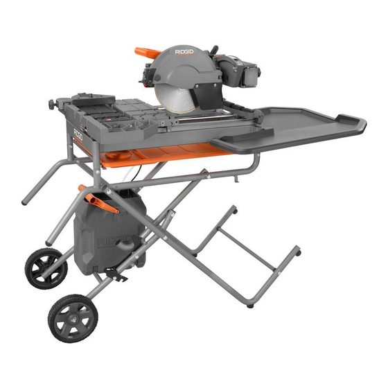
10 in. TILE SAW
R4091
Advertisement
Chapters
Table of Contents

Related Manuals for RIDGID R4091


Summary of Contents for RIDGID R4091
- Page 1 When properly cared for, it will give you years of rugged, trouble-free performance. WARNING: To reduce the risk of injury, the user must read and understand the operator’s manual before using this product. Thank you for buying a RIDGID product. ® SAVE THIS MANUAL FOR FUTURE REFERENCE...
-
Page 2: Table Of Contents
TABLE OF CONTENTS Introduction ..................................2 General Safety Rules ..............................3-4 Specific Safety Rules ................................ 5 Symbols .................................... 6 Electrical ..................................7-8 Features ..................................9-10 Tools Needed .................................. 10 Loose Parts ..................................11 Assembly ...................................12-19 ... -
Page 3: General Safety Rules
GENERAL SAFETY RULES ALWAYS WEAR EYE PROTECTION WITH SIDE WARNING: SHIELDS WHICH IS MARKED TO COMPLY WITH ANSI Z87.1 WHEN USING THIS PRODUCT. Read and understand all instructions. Failure to follow all instructions listed below, may result in SECURE WORK. Use clamps or a vise to hold work electric shock, fire and/or serious personal injury. - Page 4 GENERAL SAFETY RULES KEEP HANDS AWAY FROM CUTTING AREA. Keep KEEP TOOL DRY, CLEAN, AND FREE FROM OIL AND GREASE. Always use a clean cloth when cleaning. Never hands away from wheels. Do not reach underneath work or around or over the wheel while wheel is rotating. Do not use brake fluids, gasoline, petroleum-based products, or attempt to remove cut material when wheel is moving.
-
Page 5: Specific Safety Rules
SPECIFIC SAFETY RULES SECURE WORK firmly against the miter guide or fence. ALWAYS TURN OFF SAW before disconnecting it, to avoid accidental starting when reconnecting to power NEVER stand or have any part of your body in line with supply. -
Page 6: Symbols
SYMBOLS The following signal words and meanings are intended to explain the levels of risk associated with this product. SYMBOL SIGNAL MEANING Indicates an imminently hazardous situation, which, if not avoided, will result DANGER: in death or serious injury. Indicates a potentially hazardous situation, which, if not avoided, could result WARNING: in death or serious injury. -
Page 7: Electrical
ELECTRICAL EXTENSION CORDS ELECTRICAL CONNECTION Use only 3-wire extension cords that have 3-prong grounding This tool is powered by a precision built electric motor. It plugs and 3-pole receptacles that accept the tool’s plug. should be connected to a power supply that is 120 V, AC only (normal household current), 60 Hz. - Page 8 ELECTRICAL If the saw is used with an extension cord, ensure the connection of the tool’s power cord and the extension cord are not on the ground. If a protected outlet is not available, do not use the saw until an outlet can be changed or auxiliary protection can be obtained.
-
Page 9: Features
FEATURES PRODUCT SPECIFICATIONS Wheel Diameter ............10 in. Diagonal Capacity (tile size) ........24 in. Wheel Arbor .............. 5/8 in. Maximum Depth of Cut ......... 3-3/4 in. Throat Capacity ............17 in. Rating ...........120 V~, 15 Amps, 60 Hz Rip Capacity (tile size) ..........34 in. No Load Speed ........4,500 r/min. -
Page 10: Tools Needed
FEATURES MICRO-CUT FENCE SUPPORT - This machined ledge KNOW YOUR TILE SAW helps prevent tile from cracking. See Figure 3. MITER GUIDE - The easy-to-read indicator on the miter The safe use of this product requires an understanding of guide shows the exact angle for a miter cut with detents at the information on the tool and in this operator’s manual as 0°, 22.5°, and 45°. -
Page 11: Loose Parts
LOOSE PARTS The following items are included with your tile saw: Fig. 5 A - Water tray frame ............... 1 S - Spacer ................8 B - Tile cutting wheel .............. 1 T - Lock nut (small) ............... 8 C - Motor head assembly ............1 U - Carriage bolt .............. -
Page 12: Assembly
ASSEMBLY UNPACKING WARNING: See Figure 5. Do not connect to power supply until assembly is This product requires assembly. complete. Failure to comply could result in Carefully lift the saw from the carton and place on a level accidental starting and possible serious personal work surface. - Page 13 ASSEMBLY ASSEMBLING THE WSUV™ WET SAW Place the center brace on top of the inner leg assembly (curve side up) with the stop pin under the pedal assembly UTILITY VEHICLE / LEG STAND latch. See Figure 7. NOTE: The stop pins rest on top of inner leg assembly. Many of the WSUV™...
- Page 14 ASSEMBLY LOCKING/UNLOCKING THE SLIDING TABLES TABLE STOP BY-PASS See Figure 8. SLIDING TABLE To release the rear table from the frame, cut the tie-wrap. LOCK LEVER This saw has three sliding tables: front, middle, and rear. The front and rear table move together. To lock the front and rear tables: Pull the front table to the front of the water tray frame.
- Page 15 ASSEMBLY INSTALLING TH E WATER TRAY AND TRAY WATER TRAY FRAME EXTENSI ONS See Figures 10 - 12. WATER TRAY From the right side of the saw, place the water tray (drain EXTENSION plug end to the left) on the lip at the bottom of the water tray frame.
- Page 16 ASSEMBLY INSTALLING THE MITER GUIDE HOSE CLAMP See Figure 14. (PLASTIC) The miter guide can be used from both the left and right side of the cutting wheel. Place the slot on the underside of the miter guide on the sliding table fence.
- Page 17 ASSEMBLY TO CLOSE / OPEN THE WSUV™ WET SAW UTILITY VEHICLE / LEG STAND See Figures 17 - 19. Remove water tray extensions and the water tank, and any workpieces from the tool. Store. Replace the sliding table in the center of the frame and lock table in place.
- Page 18 ASSEMBLY TILE CUTTING WHEEL SPINDLE For maximum performance and safety, it is recommended LOCK that you use the 10 in. cutting wheel provided with your saw. Additional cutting wheels of the same high quality are available at your local dealer. WARNING: Do not use cutting wheels rated less than the no load speed of this tool.
- Page 19 ASSEMBLY Wipe a drop of oil onto the washer where it contacts the LASER LEFT/ LASER GUIDE RIGHT cutting wheel. SWITCH ADJUSTMENT Place an outer washer onto the spindle. The double “D” flats KNOB on the washer align with the flats on the spindle. Be sure LASER FRONT/ BACK the hollow side of the washer is against the cutting wheel.
-
Page 20: Operation
OPERATION WARNING: WARNING: Do not allow familiarity with tools to make you In the event of a power failure or when the tool is careless. Remember that a careless fraction of a not in use, turn the switch OFF. This action will second is sufficient to inflict serious injury. - Page 21 OPERATION LOCKING / UNLOCKING THE SAW ARM FOR D-HANDLE PLUNGE CUTS See Figure 25. To unlock and raise the saw arm: Push down on the “D” handle and pull out the lock pin. Firmly grasp the “D” handle and apply downward pressure while at the same time turning the lock knob counterclockwise.
- Page 22 OPERATION D-HANDLE TO CHANGE CUTTING WHEEL DEPTH See Figure 28. The depth stop limits the wheel’s downward travel allowing the wheel to go below the table enough to maintain full cutting capacities. When the saw arm is locked in the down DEPTH STOP position, this is the position for all cuts except for plunge cuts and non-through cuts.
- Page 23 OPERATION MAKING CUTS CROSS CUT / RIP CUT Always draw the line to be cut on the tile using a marker or MARK grease pencil. If the tile is shiny and hard-to-mark, place MITER masking tape on the tile and mark the tape. GUIDE A common problem when cutting tile is straying from the marked line.
- Page 24 OPERATION TO MAKE A MITER CUT MITER CUT See Figure 33. Miter cuts are used for cutting outside and inside corners on material, with the material at any angle to the wheel other than 90°. Miter cuts tend to “creep” during cutting. This can be controlled by holding the workpiece securely against the miter guide.
- Page 25 OPERATION Turn the material over and make the cut along one of the Slowly lower the motor head into the material to make marks. This time overcut the other line and the cut piece the cut. should separate from the rest of the material. Raise the motor head.
- Page 26 OPERATION MAKING GARDEN PAVER CUTS See Figures 37 - 40. Garden pavers require special cuts to make curves and corners in walls, patios, and other landscaping features. To cut paver shorter: Measure paver to determine how much material needs to be removed.
- Page 27 OPERATION To make paver for corners: Measure paver and landscaping feature to determine how much material needs to be removed and how much of an angle is required for wall corner. Using grease pencil and square, draw a mark from center of brick to corner, marking all the way around the paver.
-
Page 28: Adjustments
ADJUSTMENTS LEFT RAIL HEX KEY WARNING: Before performing any adjustment, make sure the tool is unplugged from the power supply and the switch is in the OFF position. Failure to heed this warning could result in serious personal injury. The saw has been adjusted at the factory for making very SCREW accurate cuts. - Page 29 ADJUSTMENTS POSITIVE STOP ADJUSTMENTS See Figure 43. NOTE: These adjustments were made at the factory and normally do not require readjustment. Unplug the saw. If the cutting wheel is not perfectly vertical (0°): Loosen the bevel lock knob. ...
-
Page 30: Maintenance
MAINTENANCE Check for wear. Replace both brushes when either has WARNING: less than 1/4 in. length of carbon remaining. Do not replace one side without replacing the other. When servicing, use only identical replacement parts. Use of any other parts may create a hazard ... - Page 31 MAINTENANCE CLEANING THE SAW NOTE: To maintain efficiency and extend the life of the pump, check intake screen before use to make sure it is See Figure 45. clean. Unplug the saw and water pump. Rinse filter with clean water Unlock table stop (turning until the slot is horizontal).
-
Page 32: Warranty
Some states do not allow limitations on how long mal wear items such as brushes, chucks, motors, switches, an implied warranty lasts and/or do not allow the exclusion cords, gears and even cordless batteries in this RIDGID ® or limitation of incidental or consequential damages, so the tool for three years following the purchase date of the tool. - Page 33 Correctement entretenue, elle vous donnera des années de fonctionnement robuste et sans problème. AVERTISSEMENT : Pour réduire les risques de blessures, l’utilisateur doit lire et veiller à bien comprendre le manuel d’utilisation avant d’utiliser ce produit. Merci d’avoir acheté un produit RIDGID ® CONSERVER CE MANUEL POUR FUTURE RÉFÉRENCE 1 — Français...
- Page 34 TABLE OF CONTENTS Introduction ..................................2 Règles de sécurité générales ............................3-4 Règles de sécurité particulières ............................5 Symboles ..................................6 Caractéristiques électriques ............................7-8 Caractéristiques ................................9-10 Outils nécessaires ................................10 Piéces détachées ................................11 ...
-
Page 35: Règles De Sécurité Générales
RÈGLES DE SÉCURITÉ GÉNÉRALES PORTER UNE TENUE APPROPRIÉE. Ne pas porter de AVERTISSEMENT : vêtements amples, cravates, ou bijoux susceptibles de se prendre et vous entraîner dans les pièces mobiles. Des Lire et veiller à bien comprendre toutes les gants en caoutchouc et des chaussures antidérapantes instructions. - Page 36 RÈGLES DE SÉCURITÉ GÉNÉRALES NE PAS MODIFIER la fiche fournie. Si elle ne peut pas NE PAS MALTRAITER LE CORDON D’ALIMENTATION. être insérée dans la prise secteur, faire installer une prise Ne jamais tirer sur le cordon pour le débrancher de la adéquate par un électricien qualifié.
-
Page 37: Règles De Sécurité Particulières
RÈGLES DE SÉCURITÉ PARTICULIÈRES Les avertissements ci-dessous doivent être apposés sur TOUJOURS ASSUJETTIR LA PIÈCE À COUPER CET OUTIL : fermement contre le guide d’onglet ou le guide. NE JAMAIS se tenir ou laisser une partie du corps se a) Porter une protection oculaire, auditive et respiration. -
Page 38: Symboles
SYMBOLES Les termes de mise en garde suivants et leur signification ont pour but d’expliquer le degré de risques associé à l’utilisation de ce produit. SYMBOLE SIGNAL SIGNIFICATION Indique une situation extrêmement dangereuse qui, si elle n’est pas évitée, DANGER : aura pour conséquences des blessures graves ou mortelles. -
Page 39: Caractéristiques Électriques
CARACTÉRISTIQUES ÉLECTRIQUES CORDONS PROLONGATEURS AVERTISSEMENT : Utiliser exclusivement des cordons prolongateurs à 3 fils doté Vérifier l’état des cordons prolongateurs avant d’une fiche à prise de terre branchés sur une prise triphasée chaque utilisation. Remplacer immédiatement tout compatible avec la fiche de l’outil. Lors de l’utilisation d’un cordon endommagé. - Page 40 CARACTÉRISTIQUES ÉLECTRIQUES Consulter un électricien qualifié ou le personnel de service si les instructions de mise à la terre ne sont pas bien comprises, ou en cas de doute au sujet de la mise à la terre. Tout cordon endommagé doit être réparé ou remplacé immédiatement.
-
Page 41: Caractéristiques
CARACTÉRISTIQUES FICHE TECHNIQUE Diamètre de la lame........... 10 po Capacité de diagonale (carreaux la taille) ....24 po Arbre de la lame ............5/8 po Profondeur de coupe maximum ......3-3/4 po Capacité de la gorge ..........17 po Alimentation nominale ......120 V~, 15 A, 60 Hz Capacité... -
Page 42: Outils Nécessaires
CARACTÉRISTIQUES POUR SE FAMILIARISER AVEC LA SCIE À SUPPORT DU GUIDE À MICRO-COUPES - Le guide pour empêcher les carreaux de se fissurer. CARREAUX GUIDE D’ONGLET - Le rapporteur facile à lire indique l’angle Voir la figure 3. exact pour la coupe d’onglet et présente des cran d’arrêt à 0°, L’utilisation sûre de ce produit exige une compréhension des 22,5°... - Page 43 PIÈCES DÉTACHÉES Les composants suivants sont inclus avec votre scie à carreaux : Fig. 5 A - Bâti d’eau ................1 S - Pièce d’écartement ............8 B - Meule à carreaux .............. 1 T - Écrou de blocage (petite) ..........8 C - Ensemble du moteur de tête ..........
-
Page 44: Assemblage
ASSEMBLAGE ATTACHER LE POIGNEE RÉSERVOIR D’EAU DÉBALLAGE Voir la figure 6. Voir la figure 5. Ce produit doit être assemblé. La poignée devrait être attachée au réservoir d’eau. Des deux côté du réservoir d’eau sont des fentes être utilisées Sortir soigneusement la scie du carton et la poser sur un pour l’installation de poignée. - Page 45 ASSEMBLAGE ASSEMBLAGE DE CHARIOT UTILITAIRE POUR Placer l’entretoise centrale sur le dessus de l’ensemble de pattes internes (le côté courbé vers le haut) et placer SCIE À CARREAUX SOUS EAU WSUV™ / la goupille de butée du loquet de l’ensemble pédale. STAND NOTE : Le goupille de butée le repos sur l’assemblée Voir la figure 7.
- Page 46 ASSEMBLAGE BUTÉE DE VERROUILLAGE/DÉVERROUILLER DES LEVIER DE TABLE DE VERROUILLAGE DE TABLES COULISSANTE DÉVIATION TABLE COULISSANTE Voir la figure 8. Para liberar el table de arrière l’arrière du cadre, couper l’attache-emballaant. Cette scie a trois tables de coulissante : le avant, le centre, et l’arrière.
- Page 47 ASSEMBLAGE INSTALLATION PLATEAU D’EAU ET PLATEAU BÂTI D’EAU L’EXTENSION PLATEAU Voir les figures 11 - 13. D’EAU À partir du côté droit de la scie, placer le plateau à L’EXTENSION eau (l’extrémité du bouchon de vidange située vers la gauche) sur la lèvre située au bas du cadre du plateau à...
- Page 48 ASSEMBLAGE INSTALLATION GUIDE D’ONGLET COLLIER DE Voir la figure 14. LA TUYAU (PLASTIQUE) Le guide d’onglet peut être utilisé de la gauche et de la droit du côté de la muele de coupe. Placer la fente en dessous du guide d’onglet du guide de la table coulissante.
- Page 49 ASSEMBLAGE POUR FERMER ET OUVRIR DE CHARIOT Une fois le stand libéré du levier de blocage, abaisser lentement le stand vers le sol en poussant les prises UTILITAIRE POUR SCIE À CARREAUX SOUS vers le sol. EAU WSUV™ / STAND ...
- Page 50 ASSEMBLAGE MEULE À CARREAUX Para rendement maximum et sécurité, Il est conseillé de n’utiliser que le muele de coupe 10 po est fournie avec la BOUTON DE scie.Il existe d’autres modèles de mueles de la même qualité VERRROUILLAGE prévues pour votre distributeur local. DE LA BROCHE AVERTISSEMENT : Ne pas utiliser de mueles dont la vitesse à...
- Page 51 ASSEMBLAGE Appliquer une goutte d’huile sur la surface de contact Desserrer le bouton de verrouillage du laser. des rondelles intérieure. Tourner le laser le mouvement de bouton d’ajustement Remettre en place la rondelle extérieure sur la meule gauche/droite la ligne laser gauche ou à...
-
Page 52: Utilisation
UTILISATION COMMUTATEUR DE POMPE EN AVERTISSEMENT : POSITION DE MARCHE AVEC COMMUTATEUR Ne pas laisser la familiarité avec l’outil faire oublier COMMUTATEUR DE MARCHE/ ARRÊT (A DE la prudence. Ne pas oublier qu’une fraction de POMPE TOUJOURS POSITION) EN POSITION seconde d’inattention peut entraîner des blessures DE MARCHE (B DE graves. - Page 53 UTILISATION COMMUTATEUR MARCHE / ARRÊT AVERTISSEMENT : Voir la figure 24. Pour éviter un démarrage accidentel, TOUJOURS Ce produit est équipé d’un commutateur avec dispositif de s’assurer que le commutateur est en position verrouillage intégré. Ce dispositif est conçu pour empêcher D’ARRÊT avant de brancher l’outil.
- Page 54 UTILISATION VERROUILLAGE/DÉVERROUILLAGE DU BRAS POIGNÉE DE LA SCIE POUR COUPES PLONGEANTE EN « D » Voir la figure 25. Pour déverrouiller et relever le bras de la scie : Appuyer sur le poignée en « D » et tirer la goupille de verrouillage.
- Page 55 UTILISATION POIGNÉE EN RÉGLAGE DE LA PROFONDEUR DE MEULE « D » DE COUPE Voir la figure 28. BUTÉE DE La butée de profondeur limite la course de la muele vers le bas PROFONDEUR permettant à la muele de descendre suffisamment au-dessous de la table pour assurer la coupe de toute l’épaisseur des pièces.
- Page 56 UTILISATION COUPE TRANSVERSALE / REFENTE EXÉCUTION DE COUPES Toujours dessiner la ligne être coupée sur le carreaux utilisant MARQUER un crayon de borne ou graisse. Si le carreaux est brillant et GUIDE dur-à-la marque, le lieu masquant la bande sur le carreau et D’ONGLET marque la bande.
- Page 57 UTILISATION COUPE D’ONGLET POUR EFFECTUER UNE COUPE D’ONGLET Voir la figure 33. Une coupe d’onglet pour couper les coins intérieures et extérieures de tuiles, avec le matériel à n’importe quel angle à la roue autrement que 90°. Les coupes d’onglet ont tendance à «...
- Page 58 UTILISATION POUR EFFECTUER UNE COUPE BISEAU COUPE EN BISEAU Voir la figure 35. Les coupes biseau peuvent être faites de 22,5° et 45° les angles. La scie s’engage d’elle-même dans l’une les points de référence LEVIER DE dans 0°, 22.5°, or 45°. VERROUILLAGE ...
- Page 59 UTILISATION POUR EFFECTUER LA COUPE DE PIERRE À JARDIN Voir les figures 37 - 40. Les pierres à jardin nécessitent une coupe spéciale pour obtenir des courbes et des coins pour pouvoir s’adapter aux murs, terrasses et autres configurations de l’aménagement paysager.
- Page 60 UTILISATION Faire des coupes de pierre pour les coins : Mesurer la pierre et la caractéristique de l’aménagement paysager afin de déterminer la qualité de matériau à enlever et déterminer l’angle requis pour le coin de mur. Faire une marque à partir du centre de la brique jusqu’au coin à...
-
Page 61: Réglages
RÉGLAGES CLÉ RAIL HEX. AVERTISSEMENT : GAUCHE RAIL Avant d’effectuer tout réglage, s’assurer que l’outil DROIT est débranché et que son commutateur est en position d’ARRÊT (OFF). Le non-respect de cet avertissement pourrait entraîner des bles- sures graves. D’ARRÊT Cette scie à table a été réglée en usine pour effectuer des coupes très précises. - Page 62 RÉGLAGES Une fois que les rouleaux s’appuient contre le rail, ser- rer solidement l’écrou du boulon à came. Répéter cette opération pour chaque rouleau, au besoin. NOTE : Vérifier que les rouleaux glissent de manière ap- propriée après chaque réglage. RÉGLAGES DE BUTÉE POSITIVE BOUTON DE Voir la figure 43.
-
Page 63: Entretien
ENTRETIEN Regarder s’ils sont usés. Remplacer les deux balais AVERTISSEMENT : lorsque la longueur du carbone est de 6 mm (1/4 po) ou moins. Ne pas remplacer un balai sans remplacer l’autre. Utiliser exclusivement des pièces identiques à celles d’origine pour les réparations. L’usage ... - Page 64 ENTRETIEN NETTOYER DE RAILS NETTOYAGE DE LA POMPE Débrancher la pompe avant de la manipuler ou de la Pendant l’usage, la rails deviendra empêcher sale les nettoyer. rouleaus de table du glissement facilement. C’est important de nettoyer la rails souvent. Lubrifier avec le pétrole léger ...
-
Page 65: Garantie
être adressées à One World Technologies, une centre de service autre qu’un centre de réparation Inc., aux soins de : Service technique des outils motorisés agréé d’outils motorisés à main et d’établi RIDGID ® à main et d’établi RIDGID... - Page 66 ADVERTENCIA: Para reducir el riesgo de lesiones, el usuario debe leer y comprender el manual del operador antes de usar este producto. Le agradecemos la compra de un producto RIDGID ® GUARDE ESTE MANUAL PARA FUTURAS CONSULTAS 1 — Español...
- Page 67 TABLE OF CONTENTS Introducción ..................................2 Reglas de seguridad generales .............................3-4 Reglas de seguridad específicas ............................5 Símbolos ................................... 6 Aspectos eléctricos ...............................7-8 Características ................................9-10 Herramientas necesarias ..............................10 Piezas sueltas ................................. 11 ...
-
Page 68: Reglas De Seguridad Generales
REGLAS DE SEGURIDAD GENERALES que los conductores sean de calibre 14 (A.W.G.) por lo ADVERTENCIA: menos, para un cordón de extensión de 7,6 metros (25 Lea y comprenda todas las instrucciones. El pies) de largo o menos. Si tiene dudas, utilice un cordón incumplimiento de las instrucciones señaladas del calibre más grueso siguiente. - Page 69 REGLAS DE SEGURIDAD GENERALES CONSULTE A UN ELECTRICISTA CALIFICADO o AVANCE LA PIEZA DE TRABAJO EN LA DIRECCIÓN técnico de servicio si no ha comprendido completamente CORRECTA. Solamente empuje la pieza de trabajo hacia las instrucciones de conexión a tierra o si no está seguro la hoja, fresa o tambor de lijado, contra el sentido de de que la herramienta está...
-
Page 70: Reglas De Seguridad Específicas
REGLAS DE SEGURIDAD ESPECÍFICAS ASEGURE LA PIEZA DE TRABAJO firmemente contra ESTA HERRAMIENTA tendrá los siguientes avisos: guía de ingletes o la guía. a) Póngase protección ocular, oídos y respirar. NUNCA se pare ni tenga ninguna parte del cuerpo en b) Utilice protección de la muela para cada operación línea con la trayectoria de la hoja de la sierra. -
Page 71: Símbolos
SÍMBOLOS Las siguientes palabras de señalización y sus significados tienen el objeto de explicar los niveles de riesgo relacionados con este producto. SÍMBOLO SEÑAL SIGNIFICADO Indica una situación peligrosa inminente, la cual, si no se evita, causará PELIGRO: la muerte o lesiones serias. Indica una situación peligrosa posible, la cual, si no se evita, podría causar ADVERTENCIA: la muerte o lesiones serias. -
Page 72: Aspectos Eléctricos
ASPECTOS ELÉCTRICOS CABLES DE EXTENSIÓN ADVERTENCIA: Sólo utilice cables de extensión de 3 conductores con clavijas Inspeccione los cables de extensión cada vez de tres puntas y contactos de tres polos que acepten la clavija antes de usarlos. Si están dañados, reemplácelos del cable de la herramienta. - Page 73 ASPECTOS ELÉCTRICOS Consulte a un electricista calificado o técnico de servicio si no ha comprendido completamente las instrucciones de conexión a tierra o si no está seguro si la herramienta está bien conectada a tierra. Repare o reemplace de inmediato todo cordón dañado o gastado.
-
Page 74: Características
CARACTERÍSTICAS ESPECIFICACIONES DEL PRODUCTO Capacidad de diagonale (tamaño de losas) ..24 pulg. Diámetro de la hoja ..........10 pulg. Árbol de la hoja ............ 5/8 pulg. Profundidad del corte máxima ......3-3/4 pulg. Capacidad de la garganta ........17 pulg. Potencia nominal .........120 V~, 15 A, 60 Hz Velocidad en vacio .........4 500 r/min (RPM) Capacidad de corte al hilo (tamaño de losas) .. -
Page 75: Herramientas Necesarias
CARACTERÍSTICAS FAMILIARÍCESE CON LA SIERRA DE LOSAS SOPORTE DE GUÍA PARA CORTES MICROSCÓPICOS - Este guía ayuda a evitar que la losa se rompa. Vea la figura 3. GUÍA DE INGLETES - Este indicador de fácil lectura muestra El uso seguro que este producto requiere la comprensión de el ángulo exacto para cortes a inglete, y tiene trinquete a la información impresa en la herramienta y en el manual del 0°, 22,5°, y 45°. -
Page 76: Piezas Sueltas
PIEZAS SUELTAS Con la sierra de losas vienen incluidos los siguientes artículos: Fig. 5 A - Agua en la armazón ............1 S - Separador ................. 8 B - Muela para cortar losas ............ 1 T - Tuerca de seguridad (pequeña) ........8 C - Conjunto del motor de cabeza .......... -
Page 77: Armado
ARMADO DESEMPAQUETADO ADVERTENCIA: Vea la figura 5. No conecte la unidad a la toma de corriente antes Este producto requiere armarse. de terminar de armarla. De lo contrario, la unidad Extraiga cuidadosamente de la sierra y colóquela sobre puede ponerse en marcha accidentalmente, con una superficie de trabajo nivelada. - Page 78 ARMADO ARMADO DE CARRO PARA SERVICIO PARA Coloque la riostra central sobre el conjunto de la pata interior (lado de la curva hacia arriba) con el pasador de SIERRAS HÚMEDAS WSUV™ / PEDESTAL tope por debajo del pestillo del conjunto del pedal. Vea la figura 7.
- Page 79 ARMADO ASEGURAR/DESBLOQUEAR LAS MESAS TOPE DE LA MESA DE PUENTE DESLIZABLE PALANCA DE FIJACIÓN Vea la figura 8. DE LA MESA DESLIZABLE Pour le libérer la mesa trasera del marco, couper l’attache. Este sierra tiene tres mesas que deslizan: frente, el mitad, y trasero.
- Page 80 ARMADO RETIRER / INSTALAR LA BANDEJA DE AGUA EN LA ARMAZÓN PARTÍCULAS Y BADEJAS DE EXTENSIÓN Vea las figuras 11 - 13. BANDEJAS DE Desde el lado derecho de la sierra, coloque la bandeja AGUA DE de agua (extremo del tapón de drenaje hacia la izquierda) EXTENSIÓN sobre el reborde en la parte inferior del armazón de la bandeja de agua.
- Page 81 ARMADO INSTALAR GUÍA DE INGLETES ABRAZADERAS DE Vea la figura 14. MANGUERA (PLÁSTICO) La guía de borde al hilo puede ser utilizada de la izquierda y a la derecha el lado correcto de la muela para cortar. Coloque la ranura de la parte inferior de la guía de ingletes sobre la guía de corte de la mesa deslizante.
- Page 82 ARMADO PARA PLEGAR Y ABRIR DE CARRO PARA SERVICIO PARA SIERRAS HÚMEDAS WSUV™ / PEDESTAL Vea las figuras 17 - 19. Quite bandejas de agua de extensións y tanque de agua y retire de la herramienta toda pieza de trabajo presente. Guarde.
- Page 83 ARMADO MUELA PARA CORTAR LOSAS BLOQUEO DEL Para un mayor rendimiento y seguridad, se recomienda que HUSILLO use solamente 10 pulg. muela para cortar es suministrada con la sierra. Se dispone de estilos adicionales de muelas de la misma alta calidad para su distribuidor local. ADVERTENCIA: Asegúrese de usar únicamente muelas con velocidad en vacio nominal mínima inferior a la...
- Page 84 ARMADO Unte una gota de aceite en las arandelas interior, donde Gire la perilla de ajuste del láser izquierdo y derecha de tocan ésta. ajuste la línea de láser o izquierda o el derecho. Vuelva arandela exterior. Las dos partes planas en forma ...
-
Page 85: Funcionamiento
FUNCIONAMIENTO INTERRUPTOR DE ADVERTENCIA: BOMBA EN POSICIÓN DE ENCENDIDO CON No permita que su familarización con las INTERRUPTOR DE herramientas lo vuelva descuidado. Tenga presente INTERRUPTOR DE ENCENDIDO/APAGADO BOMBA SIEMPRE que un descuido de un instante es suficiente para (POSICIÓN A) EN POSICIÓN causar una lesión seria. - Page 86 FUNCIONAMIENTO INTERRUPTOR DE ENCENDIDO/APAGADO ADVERTENCIA: Vea la figura 24. Para reducir el riesgo de un arranque accidental, Esta sierra está equipada con un conjunto del interruptor SIEMPRE asegúrese de que el interruptor esté en de corriente dotado de cerradura de llave integrada. Esta la posición de APAGADO antes de conectar la característica tiene la finalidad de evitar el uso no autorizado herramienta en la toma de corriente.
- Page 87 FUNCIONAMIENTO PROCEDIMIENTO DE TRABA Y DESTRABA MANGO EN “D” EL BRAZO DE LA SIERRA PARA CORTES DE PENETRACIÓN Vea la figura 25. Para destrabar y levantar el brazo de la sierra: Empújelo hacia abajo por la manga en “D” y extraiga el pasador de seguridad.
- Page 88 FUNCIONAMIENTO PARA CAMBIAR LA PROFUNDIDAD DE LA MUELA PARA CORTAR Vea la figura 28. MANGO EN “D” TOPE DE El tope de profundidad limita el desplazamiento hacia abajo PROFUNDIDAD de la hoja permite que la hoja sobrepase la mesa lo suficiente para mantener completa la capacidad de corte.
- Page 89 FUNCIONAMIENTO FORMA DE EFECTUAR CORTES Deje que la muela para cortar adquiera velocidad y espera para la rueda para mojar antes de mover la mesa de Siempre escriba la línea para ser cortada en el losa que inglete para alimentar la pieza de trabajo a la muela. utiliza un lápiz de marcador o grasa.
- Page 90 FUNCIONAMIENTO CORTE A INGLETE Cuando termine el corte, apague la sierra; para ello, ponga el botón en la posición APAGADO. Espere a que la muela se detenga por completo antes de retirar cualquier parte de la material. PARA EFECTUAR CORTES A INGLETE Vea la figura 33.
- Page 91 FUNCIONAMIENTO Coloque el válvula de ajuste del flujo en la posición de Cuando termine el corte, apague la sierra; para ello, ponga el botón en la posición APAGADO. Espere a que la muela ENCENDIDO. se detenga por completo antes de retirar cualquier parte ...
- Page 92 FUNCIONAMIENTO CORTAR ADOQUINES DE JARDÍN Vea las Figuras 37 - 40. Los adoquines de jardín requieren cortes especiales para realizar curvas y esquinas en paredes, patios y otras obras de paisajismo. Para acortar el adoquín: Mida el adoquín para determinar cuánto material es necesario quitar.
- Page 93 FUNCIONAMIENTO Cortar adoquines para esquinas: Mida el adoquín y la obra de paisajismo para determinar cuánto material es necesario quitar y qué ángulo se necesita para la esquina. Con un lápiz de cerca y una escuadra, dibuje una marca desde el centro del adoquín hacia la esquina;...
-
Page 94: Ajustes
AJUSTES RIEL IZQUIERDO ADVERTENCIA: RIEL Antes de efectuar cualquier ajuste, asegúrese DERECHO LLAVE de que la herramienta esté desconectada del HEXAGONAL suministro de corriente y de que el interruptor esté en la posición de APAGADO (OFF). La falta de atención a esta advertencia podría causar lesiones TORNILLO corporales graves. - Page 95 AJUSTES Para ajustar si la mesa es aflojar: Afloje la tuerca del perno de la leva. Inserto llave hexagonal por el hoyo en el lado izquierdo de la mesa. Estos pernos que ejes pueden ser ajustes hacia arriba y abajo en la perno. ...
-
Page 96: Mantenimiento
MANTENIMIENTO Efectúe una inspección para ver si hay desgaste. ADVERTENCIA: Reemplace ambas escobillas cuando una u otra tenga menos de 6 mm (1/4 pulg.) de carbón restante. No Al dar servicio a la unidad, sólo utilice piezas de reemplace un solo lado sin reemplazar el otro. repuesto idénticas. - Page 97 MANTENIMIENTO LIMPIEZA EL SIERRA NOTA : Para mantener la eficiencia y extender la duración de la bomba, verifique el cedazo de la entrada antes del Vea la figura 45. uso para asegurarse de que esté limpio. Desconecte la sierra y bomba de agua. ...
-
Page 98: Garantía
GARANTÍA HERRAMIENTAS ELÉCTRICAS DE MANO Y ESTACIONARIAS RIDGID ® GARANTÍA DE SERVICIO LIMITADA DE TRES AÑOS One World Technologies, Inc. P.O. Box 35, Hwy. 8 Pickens, SC 29671, USA 33 — Español... - Page 99 NOTES/NOTAS 34 — Español...
- Page 100 SIERRA DE LOSAS DE 254 mm (10 pulg.) R4091 Customer Service Information: For parts or service, contact your nearest RIDGID authorized service center. Be ® sure to provide all relevant information when you call or visit. For the location of the authorized service center nearest you, please call 1-866-539-1710 or visit us online at www.ridgid.com.
Need help?
Do you have a question about the R4091 and is the answer not in the manual?
Questions and answers