Table of Contents
Advertisement
Your saw has been engineered and manufactured to our high standard for dependability, ease of operation, and operator
safety. When properly cared for, it will give you years of rugged, trouble-free performance.
WARNING:
To reduce the risk of injury, the user must read and understand the operator's manual before using this product.
SAVE THIS MANUAL FOR FUTURE REFERENCE
Cette scie a été conçue et fabriquée conformément aux strictes
normes de fiabilité, simplicité d'emploi et sécurité d'utilisation.
Correctement entretenu, cet outil vous donnera des années de
fonctionnement robuste et sans problème.
AVERTISSEMENT :
Pour réduire les risques de blessures, l'utilisateur
doit lire et veiller à bien comprendre le manuel
d'utilisation avant d'employer ce produit.
CONSERVER CE MANUEL POUR
FUTURE RÉFÉRENCE
OPERATOR'S MANUAL
MANUEL D'UTILISATION
MANUAL DEL OPERADOR
SCIE À TABLE de 254 mm (10 po)
SIERRA DE MESA de 254 mm (10 pulg.)
Su sierra ha sido diseñado y fabricado de conformidad con
nuestras estrictas normas para brindar fiabilidad, facilidad de
uso y seguridad para el operador. Con el debido cuidado, le
brindará muchos años de sólido funcionamiento y sin problemas.
ADVERTENCIA:
Para reducir el riesgo de lesiones, el usuario debe
leer y comprender el manual del operador antes de
usar este producto.
GUARDE ESTE MANUAL PARA
FUTURAS CONSULTAS
10 in. TABLE SAW
R4520/R4520T
To register your RIDGID
product, please visit:
http://register.RIDGID.com
Pour enregistrer votre
produit de RIDGID,
s'il vous plaît la visite :
http://register.RIDGID.com
Para registrar su producto
de RIDGID, por favor visita:
http://register.RIDGID.com
Advertisement
Table of Contents

Subscribe to Our Youtube Channel
Related Manuals for RIDGID R4520


Summary of Contents for RIDGID R4520
- Page 1 : http://register.RIDGID.com Para registrar su producto de RIDGID, por favor visita: http://register.RIDGID.com Your saw has been engineered and manufactured to our high standard for dependability, ease of operation, and operator safety. When properly cared for, it will give you years of rugged, trouble-free performance.
- Page 2 TABLE OF CONTENTS TABLE DES MATIÈRES / ÌNDICE DE CONTENIDO Introduction ..................................2 Introduction / Introducción General Safety Rules ..............................3-4 Règles de sécurité générales / Reglas de seguridad generales Table Saw Safety Rules ..............................4-6 Règles de sécurité scie à table / Reglas de seguridad sierra de mesa ...
- Page 3 GENERAL SAFETY RULES Use personal protective equipment. Always wear eye WARNING: protection. Protective equipment such as dust mask, non-skid safety shoes, hard hat, or hearing protection used Read all safety warnings, instructions, for appropriate conditions will reduce personal injuries. illustrations and specifications provided with this power tool.
- Page 4 GENERAL SAFETY RULES Keep cutting tools sharp and clean. Properly maintained Keep handles and grasping surfaces dry, clean and cutting tools with sharp cutting edges are less likely to free from oil and grease. Slippery handles and grasping bind and are easier to control.
- Page 5 TABLE SAW SAFETY RULES Provide auxiliary workpiece support to the rear and/or Use extra caution when making a cut into blind areas sides of the saw table for long and/or wide workpieces of assembled workpieces. The protruding saw blade to keep them level.
- Page 6 TABLE SAW SAFETY RULES Make sure that the saw blade is installed to rotate Never use damaged or incorrect saw blade mounting in the proper direction. Do not use grinding wheels, means such as flanges, saw blade washers, bolts or wire brushes, or abrasive wheels on a table saw.
- Page 7 SYMBOLS The following signal words and meanings are intended to explain the levels of risk associated with this product. SYMBOL SIGNAL MEANING Indicates a hazardous situation, which, if not avoided, will result in death or DANGER: serious injury. Indicates a hazardous situation, which, if not avoided, could result in death or WARNING: serious injury.
- Page 8 ELECTRICAL EXTENSION CORDS SPEED AND WIRING Use only 3-wire extension cords that have 3-prong grounding The no-load speed of this tool is approximately 3,450 rpm. This speed is not constant and decreases under a load or plugs and 3-pole receptacles that accept the tool's plug. with lower voltage.
- Page 9 GLOSSARY OF TERMS Anti-Kickback Pawls (radial arm and table saws) Pilot Hole (drill presses and scroll saws) A device which, when properly installed and maintained, A small hole drilled in a workpiece that serves as a guide is designed to stop the workpiece from being kicked back for drilling large holes accurately or for insertion of a scroll toward the front of the saw during a ripping operation.
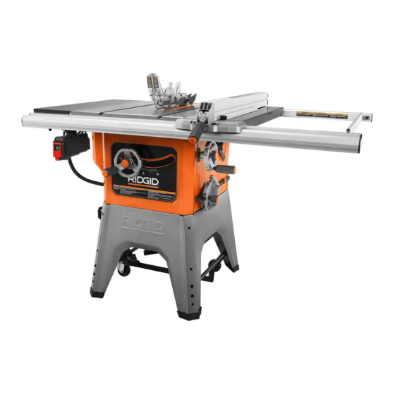
- Page 10 FEATURES PRODUCT SPECIFICATIONS Blade Arbor ...............5/8 in. No Load Speed ........3,450/min (RPM) Blade Diameter ............10 in. Cutting Depth at 0º: ..........3-1/8 in. Blade Tilt ..............0˚ - 45˚ Cutting Depth at 45º: ..........2-1/4 in. Rating ..........120 V ~, 13 Amps, 60 Hz BLADE GUARD ASSEMBLY RIVING KNIFE...
- Page 11 FEATURES ANTI-KICKBACK PAWLS, RIVING KNIFE, AND BLADE GUARD STORAGE AREA BLADE AND WRENCH STORAGE AREA MITER GAUGE STORAGE AREA RIP FENCE PUSH STORAGE STICK BRACKETS Fig. 3 KNOW YOUR TABLE SAW BLADE - For maximum performance, it is recommended that you use the 10 in. carbide tipped combination blade See Figures 2 - 3.
- Page 12 FEATURES MITER GAUGE - The miter gauge aligns the workpiece for TO TURN YOUR SAW ON: a cross cut. The easy-to-read indicator shows the exact Press the top button on the switch to turn the saw on. angle for a miter cut, with adjustable stops at 90° and 45°. NOTE: If AC power is disconnected or interrupted while MITER GAUGE GROOVES - The miter gauge rides in the the saw is running, the saw will turn off.
- Page 13 TOOLS NEEDED The following tools (not included or drawn to scale) are needed for assembly and adjustments: FRAMING SQUARE PHILLIPS SCREWDRIVER FLATHEAD SCREWDRIVER COMBINATION SQUARE SOCKET WRENCH (8 mm, 13 mm SOCKET) WRENCH 4 mm, 8 mm, 10 mm, 13 mm, 14 mm C-CLAMPS Fig.
- Page 14 LOOSE PARTS The following items are included with the table saw: 14 - English...
- Page 15 LOOSE PARTS The following items are included with the table saw: A. Rip Fence Storage Brackets ............................2 B. Multiple Items B1. Spreader Bar ..............................1 B2. Rail Connector Bar ............................3 B3. Storage Hook ..............................1 B4. Hardware Bag w/Hex Keys (8 mm, 6 mm, 5 mm, 4 mm and 3 mm) ..............1 C.
- Page 16 ASSEMBLY UNPACKING WARNING: This product requires assembly. Do not attempt to modify this tool or create Carefully lift the saw from the carton and place it on a accessories not recommended for use with this level work surface. tool. Any such alteration or modification is misuse NOTE: This tool is heavy.
- Page 17 ASSEMBLY INSTALLING THE ADJUSTING HANDWHEELS See Figure 7 and 8. NOTE: It is helpful to place two inch-thick boards on the floor before lifting the saw table and motor housing from the box. This will make it easier to assemble parts, and to move the saw and set it upright.
- Page 18 ASSEMBLY SECURING THE DUST CHUTE TO THE SAW CABINET SCREW See Figures 9 and 10. Locate the following from the large fastener pack: SCREW Screws (M5, self-tapping) ..........2 Lift the back of the dust chute up and align the holes in the chute with the holes at the back of the saw cabinet.
- Page 19 BACK and onto the saw cabinet. The front and back legs are interchangeable. NOTE: The front and back legs have the RIDGID logo on them. Align the holes in the right leg with the holes in the front leg.
- Page 20 ASSEMBLY CASTER ASSEMBLY FRONT AXLE FOOT ASSEMBLY PEDAL BOLT BOLT CENTER REAR AXLE SUPPORT ASSEMBLY SOCKET Fig. 15 HEAD BOLT Remove the bolts and nuts from the rear and front axle assemblies. NOTE: Use two 13 mm wrenches to hold the bolt and loosen the nut.
- Page 21 ASSEMBLY Install bolts through the holes in the brackets and stand. SMALL FOOT PEDAL Thread nuts onto each bolt. Use an 8 mm wrench to hold the nuts in place and use a Phillips screwdriver to tighten the bolts. LARGE FOOT PEDAL Thread the storage hook into the saw cabinet and tighten...
- Page 22 ASSEMBLY Lock the release lever by pushing the lever down. CLOSED END Using the open end blade wrench, place the flat open BLADE WRENCH end into the flats on the arbor shaft. OPEN END BLADE Insert the closed end of the other blade wrench over the WRENCH hex nut.
- Page 23 ASSEMBLY TO CHANGE RIVING KNIFE POSITIONS See Figure 23. RELEASE LEVER This saw is shipped with a riving knife that should be placed (UNLOCKED) in the “down” position for non-through cutting and must be placed in the “up” position for all other cutting operations. CAUTION: Use caution when reaching inside the throat in the saw table.
- Page 24 ASSEMBLY TO INSTALL THE ANTI-KICKBACK PAWLS AND PAWL HANDLE BUTTON BLADE GUARD See Figures 24 - 26. ANTI-KICKBACK PAWLS WARNING: Always install the blade guard and anti-kickback pawls onto the riving knife in the “up” position to provide proper blade coverage. Installing the guarding components onto the riving knife in any other position will prevent them from working as designed, which could increase the risk of...
- Page 25 ASSEMBLY To adjust (horizontally and vertically): NOTE: Blade alignment can be adjusted for different kerf widths. Refer to: To Check and Align the Riving Knife and Remove the anti-kickback pawls, blade guard assembly, Saw Blade. Check the blade guard assembly for clearances and throat plate.
- Page 26 ASSEMBLY FRONT RAIL ASSEMBLY ASSEMBLING THE RAILS LONG RAIL See Figures 29 - 31. SECTION To assemble the front rail: RIP SCALE NOTE: Do not completely tighten set screws until all front RAIL CONNECTOR BAR rail pieces are assembled and you have made sure the rail will lie flat and level.
- Page 27 ASSEMBLY INSTALLING THE RAILS ONTO THE SAW NOTE: The remaining bolt on the right side will be used to secure the spreader bar. TABLE Insert the bolts through the holes then loosely thread nuts See Figures 32 - 37. onto each bolt.
- Page 28 ASSEMBLY Using the 6 mm hex key, tighten the four center bolts. Do not tighten completely. Thread nuts onto the outer bolts. Do not tighten completely. BOLTS To check the table and rail position: Raise the blade by unlocking the height adjusting BOLTS handwheel and turning it clockwise.
- Page 29 ASSEMBLY INSTALLING THE SPREADER BAR MOUNTING THE SWITCH ASSEMBLY See Figure 38 - 39. See Figure 40. Take the following from the large fastener pack: Take the following from the large fastener pack: Nuts (M8) ..............4 Lock washers (6 mm) ............ 2 Bolts (M8 x 20 mm for the rear rail) ......
- Page 30 ASSEMBLY STORING TABLE SAW ACCESSORIES See Figures 41 - 43. When not in use the rip fence, riving knife, wrenches, blade guard, miter gauge, anti-kickback pawls, and push stick may be stored beneath the saw table. MITER GAUGE The push stick contains a magnet. When not in use, the push MITER STORAGE stick may be stored at a convenient location on the saw.
- Page 31 OPERATION CAUSES OF KICKBACK WARNING: Kickback can occur when the blade stalls or binds, kicking Do not allow familiarity with tools to make you the workpiece back toward you with great force and speed. If careless. Remember that a careless fraction of a your hands are near the saw blade, they may be jerked loose second is sufficient to inflict serious injury.
- Page 32 OPERATION To make a push block: Keep blade guard, riving knife and ainti-kickback pawls in place and proper operation. The riving knife must be The material, shape and size of a push block can vary. For in alignment with the blade and the pawls must stop a this project, use two pieces of solid wood to make the base kickback once it has started.
- Page 33 OPERATION WORKPIECE SUPPORTS See Figure 46. When cutting with your table saw, make sure that the workpiece you are cutting is properly supported. Properly supporting the workpiece throughout the cutting process WORK not only improves the accuracy of the cut but also makes SUPPORT the cutting process safer for the user.
- Page 34 OPERATION To use a jig: stop rotating before removing the stock. Reset the rip fence and cut spaced rips into the workpiece to allow approximately Position the workpiece flat on the table with the edge 1/4 in. fingers and 1/8 in. spaces between the fingers. flush against the jig and against the stop.
- Page 35 OPERATION TYPES OF CUTS See Figure 51. There are six basic cuts: 1) the cross cut, 2) the rip cut, 3) the miter cut, 4) the bevel cross cut, 5) the bevel rip cut, and 6) the compound (bevel) miter cut. All other cuts are combinations of these basic six.
- Page 36 OPERATION HEIGHT ADJUSTING AND BEVEL ADJUSTING GULLET HANDWHEEL KNOBS The height adjusting handwheel knob and bevel adjusting handwheel knobs act as locks. To unlock either knob before making an adjustment, turn the knob counterclockwise to loosen. After making a height or bevel adjustment, turn the knob clockwise to tighten.
- Page 37 OPERATION TO ADJUST THE BEVEL INDICATOR See Figure 55. If the bevel indicator is not at zero when the saw blade is at 90°, adjust the indicator by loosening the screws and setting it at 0° on the bevel scale. Retighten the screws. SCREWS TO USE THE RIP FENCE See Figures 56 and 57.
- Page 38 OPERATION SCALE TO SET THE RIP FENCE SCALE INDICATOR TO THE BLADE INDICATOR See Figure 58. FENCE Use the indicator on the rip fence to position the fence along BLADE the scale on the front rail. NOTE: The anti-kickback pawls and blade guard assembly must be removed to perform this adjustment.
- Page 39 OPERATION ADJUSTING THE BLADE PARALLEL TO THE BLADE MITER GAUGE GROOVE (REMOVING HEEL) TOOTH See Figures 60 - 63. WARNING: The blade must be made parallel to the miter gauge groove so the wood does not bind resulting in kickback. Failure to do so could result in serious personal injury.
- Page 40 OPERATION If the distances are different: REAR PANEL Remove the blade guard, riving knife, and anti-kickback pawls. Raise the blade by unlocking the height adjusting handwheel and turning it clockwise. With a 4 mm wrench, remove the 6 screws that secure the rear panel of the saw.
- Page 41 OPERATION During use the miter gauge may move slightly left or right CROSS CUT inside the miter gauge groove. For greater accuracy, press PLACE LEFT HAND ON the miter gauge against the left or right edge of the miter WORKPIECE AND gauge groove when making cuts.
- Page 42 OPERATION REPETITIVE CROSS CUT To make repetitive cross cuts: A stop block can be used as a cut-off gauge to make repetitive cross cuts of the same length without having to mark the workpiece for each cut. The end of a stop block should always be in front of the blade.
- Page 43 OPERATION Turn the saw on. Secure the rip fence. Position the workpiece flat on the table with the edge Position the workpiece flat on the table with the edge flush against the low fence. flush against the rip fence. Let the blade build up to full speed before feeding the workpiece into the blade.
- Page 44 OPERATION MAKING A MITER CUT MITER CUT See Figure 69. BLADE STRAIGHT MITER GAUGE WARNING: ANGLED Make sure the blade guard assembly is installed and working properly to avoid possible serious injury. Set the blade to the correct depth for the workpiece. ...
- Page 45 OPERATION Let the blade build up to full speed before moving the When cutting a long or wide workpiece, place a support workpiece into the blade. the same height as the table surface in front of the saw, behind the saw, and on the sides of the saw as needed.
- Page 46 OPERATION MAKING A COMPOUND (BEVEL) MITER CUT COMPOUND (BEVEL) MITER CUT See Figure 73. PLACE RIGHT HAND ON WORKPIECE HERE WARNING: Make sure the blade guard assembly is installed and working properly to avoid possible serious injury. WARNING: The miter gauge must be on the right side of the blade to avoid trapping the wood and causing kickback.
- Page 47 OPERATION NON-THROUGH CUT Depending on the shape of the panel, use the rip fence or miter gauge. If the panel is too large to use either the BLADE rip fence or the miter gauge, it is too large for this saw. GUARD ...
- Page 48 OPERATION DADO CUT MAKING A DADO CUT See Figure 76. An optional dado throat plate is required for this procedure BLADE GUARD MITER GAUGE REMOVED (see the Accessories section of this manual and check with the retailer where the table saw was purchased). All blades and dado sets must not be rated less than the speed of this tool.
- Page 49 OPERATION CONSTRUCTING A TABLE EXTENSION See Figure 77. 27 in. 14-5/8 in. You may construct a wood table extension to support larger workpieces. The finished height of the table extension should be 1-3/4 in. The finished length and width should be 27 in.
- Page 50 ADJUSTMENTS CLOSED END WARNING: BLADE WRENCH Before performing any adjustment, make sure the OPEN END BLADE tool is unplugged from the power supply and the WRENCH top button on the switch is not depressed. Failure to heed this warning could result in serious personal injury.
- Page 51 ADJUSTMENTS TO SET THE BLADE AT 0° AND 45° 0° STOP BLADE SCREW See Figures 81 - 82. COMBINATION The angle settings of your saw have been set at the factory SQUARE and, unless damaged in shipping, should not require setting during assembly.
- Page 52 ADJUSTMENTS Lock the bevel lock knob and check the blade angle. KNOB MITER Repeat above steps to readjust and recheck blade angle GAUGE BASE as needed. Once blade is 45° to the table: Check bevel indicator. If indicator is not pointing to the 45º mark on the bevel MITER GAUGE ROD scale, loosen the screws and adjust the indicator.
- Page 53 ADJUSTMENTS If the distances are different: The rip fence should sit at 90º to the top of the saw table. If an adjustment is needed: Loosen the four screws on the rip fence. Set a framing square on the saw table next to the rip fence. Adjust the rip fence.
- Page 54 ADJUSTMENTS To check the alignment of the low fence: FRONT OF Unplug the saw. RIP FENCE Verify the blade is parallel to the miter gauge groove as COMBINATION described in the Adjusting the Blade Parallel to the Miter SQUARE Gauge Groove (Removing Heel) section in Operations.
- Page 55 MAINTENANCE LUBRICATION WARNING: This saw’s motor bearings have been packed at the factory When servicing, use only identical replacement with proper lubrication. parts. Use of any other parts could create a Clean screw threads and nuts with a solvent hazard or cause product damage.
- Page 56 MAINTENANCE CLEANING THE RIVING KNIFE LOCK LEVER RIVING KNIFE PLATES See Figure 91. The lock lever on the riving knife may become difficult to lock securely after extended use due to sawdust or debris falling into the plates. Unplug the saw. LOCK Unlock the lever to remove the riving knife.
- Page 57 ACCESSORIES Look for these accessories where you purchased this product or call 1-866-539-1710: Dado Throat Plate ............................089240038701 Flip Top Portable Work Support ..........................AC9934 WARNING: Current attachments and accessories available for use with this tool are listed above. Do not use any attachments or accessories not recommended by the manufacturer of this tool.
- Page 58 TROUBLESHOOTING Problem Cause Solution Saw does not make accurate 90˚ or Positive stops inside cabinet need Adjust positive stops. 45˚ cuts. adjusting (Bevel Cuts). Miter gauge is misaligned (Miter Cuts). Adjust the miter gauge. Height and/or bevel adjusting hand- Gears or screw post inside cabinet are Clean the gears or screw post.
- Page 59 RIDGID, Inc. All warranty communications should be abuse, neglect, alteration, modification or repair by other directed to One World Technologies, Inc., attn: RIDGID Hand than an authorized service center for RIDGID branded hand ®...
- Page 60 NÚM. DE MODELO _____________ NÚM. DE SERIE ___________________________ ONE WORLD TECHNOLOGIES, INC. P.O. Box 1427 Anderson, SC 29622, USA 1-866-539-1710 www.RIDGID.com RIDGID is a registered trademark of RIDGID, Inc., used under license. 995000838 5-28-19 (REV:02)
Need help?
Do you have a question about the R4520 and is the answer not in the manual?
Questions and answers