Table of Contents
Advertisement
Quick Links
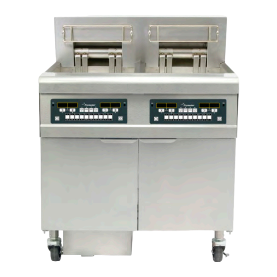
BIEL14 Series
Gen III LOV
Service and Parts Manual
This manual is updated as new information and models are released. Visit our website at
www.frymaster.com
for the latest manual.
FOR YOUR SAFETY
Do Not Store or use gasoline or other
flammable vapors and liquids in the
vicinity of this or any other appliance.
*8196963*
Part Number: FRY_SP_8196963 06/2022
Original Instructions
™
Electric Fryer
Your Growth Is Our Goal
Advertisement
Table of Contents

Related Manuals for Welbilt Frymaster McDonald's Gen III LOV BIEL14 Series


Summary of Contents for Welbilt Frymaster McDonald's Gen III LOV BIEL14 Series
- Page 1 Your Growth Is Our Goal BIEL14 Series Gen III LOV ™ Electric Fryer Service and Parts Manual This manual is updated as new information and models are released. Visit our website at www.frymaster.com for the latest manual. FOR YOUR SAFETY Do Not Store or use gasoline or other flammable vapors and liquids in the vicinity of this or any other appliance.
-
Page 2: Electrical Power Specifications
NOTICE IF, DURING THE WARRANTY PERIOD, THE CUSTOMER USES A PART FOR THIS FRYMASTER FOOD SERVICE EQUIPMENT OTHER THAN AN UNMODIFIED NEW OR RECYCLED PART PURCHASED DIRECTLY FROM FRYMASTER, OR ANY OF ITS FACTORY AUTHORIZED SERVICERS, AND/OR THE PART BEING USED IS MODIFIED FROM ITS ORIGINAL CONFIGURATION, THIS WARRANTY WILL BE VOID. -
Page 3: Table Of Contents
Table of Contents CAUTIONARY STATEMENTS ............................ii ELECTRICAL POWER SPECIFICATIONS ......................... ii CHAPTER 1: Service Procedures General ..............................1-1 Replacing a Controller ..........................1-1 Replacing Component Box Components ....................1-1 Replacing a High-Limit Thermostat ......................1-3 Replacing a Temperature Probe ......................1-3 Replacing a Heating Element ......................... - Page 4 MANUAL LOV SERIES ELECTRIC FRYERS SERVICE AND PARTS ™ TABLE OF CONTENTS cont. 2.3.2 Drain Valve Assembly ......................2-5 Electronics and Wiring Components ...................... 2-6 2.4.1 Component Boxes ......................... 2-6 2.4.2 Contactor Boxes ........................2-8 2.4.3 Heating Element Assemblies and Hardware ............... 2-10 2.4.4 Element Tube Assemblies ....................
- Page 5 MANUAL LOV™ ELECTRIC WARRANTY STATEMENT Frymaster, L.L.C. makes the following limited warranties to the original purchaser only for this equipment and replacement parts: A. WARRANTY PROVISIONS - FRYERS 1. Frymaster L.L.C. warrants all components against defects in material and workmanship for a period of two years.
- Page 6 • improper maintenance; • damage in shipment; • abnormal use; • removal, alteration, or obliteration of either the rating plate or the date code on the heating elements; • operating the frypot without shortening or other liquid in the frypot; •...
-
Page 7: Chapter 1: Service Procedures
™ MANUAL LOV SERIES ELECTRIC FRYERS CHAPTER 1: SERVICE PROCEDURES 1.1 General Before performing any maintenance on your Frymaster fryer, disconnect the fryer from the electrical power supply. WARNING To ensure the safe and efficient operation of the fryer and hood, the electrical plug must be fully engaged and locked in its pin and sleeve socket. - Page 8 2. Open the control panel by removing the screws on the bottom of the bezel. Carefully lower the bezel. 3. Remove the two screws from the upper corners of the control panel and allow the control panel to swing down. 4.
-
Page 9: Replacing A High-Limit Thermostat
1.4 Replacing a High-Limit Thermostat 1. Drain the frypots into a Shortening Disposal Unit (SDU) or other appropriate METAL container. DANGER DO NOT drain more than one full frypot into the SDU at one time. 2. Disconnect the fryer from the electrical power supply and reposition it to gain access to the rear of the fryer. - Page 10 4. Locate the red and white wires of the temperature probe to be replaced. Note where the leads are connected prior to removing them from the connector. Unplug the 12-pin connector C-6 and using a pin-pusher push the pins of the temperature probe out of the connector. 5.
-
Page 11: Replacing A Heating Element
Replacing a Heating Element 1. Perform steps 1-5 of section 1.5, Replacing a Temperature Probe. 2. Disconnect the wire harness containing the probe wiring. Using a pin pusher, disconnect the probe wires from the 12-pin connector C-6. 3. In the rear of the fryer, disconnect the 6-pin connector for the left element (as viewed from the front of the fryer) or the 9-pin connector for the right element from the contactor box. -
Page 12: Replacing Contactor Box Components
Index Marker marks Position 1 8. Reconnect the element connector ensuring that the latches lock. 9. Insert the temperature probe leads into the 12-pin wiring harness connector (see illustration below). For full-vat units or the right half of a dual-vat unit, the red lead goes into position 3 and the white into position 4. -
Page 13: Replacing A Frypot
Remove two screws to access contactor box components above the filter 4. The contactors and relays are held on by threaded pin studs so that only removal of the nut is required to replace the component. 5. After performing necessary service, reverse steps 1-4 to return the fryer to operation. Left and right views of mechanical contactor box components. - Page 14 5. Unplug the wiring harnesses and ground wires from the backs of the controllers. Remove the controllers by lifting them from the hinge slots in the control panel frame. 6. Remove the screws from the bottom of the lower back panel attaching the contactor plug guards. 7.
-
Page 15: Built-In Filtration System Service Procedures
26. Reconnect the oil return and auto top off flexlines to the frypot, and replace aluminum tape, if necessary, to secure heater strips to the flexlines. 27. Insert the high-limit thermostat leads disconnected in step 18 (see illustration on page 1-3 for pin positions). -
Page 16: Replacing The Filter Motor, Filter Pump And Related Components
Solidified shortening in the pan or filter Sediment Particle lines, or Attempting to filter unheated oil or shortening (cold oil and shortening are Oil Flow more viscous, overloading the pump motor and causing it to overheat). If the motor runs but the pump does not return oil, there is a blockage in the pump. - Page 17 3. Disconnect the flexline running to the oil-return manifold at the rear of the fryer as well as the pump suction flexline at the end of the filter pan connection (see photo below). On some models a third flexline may need to be disconnected. Disconnect flexlines indicated by the arrows.
-
Page 18: Replacing The Filter Transformer Or Filter Relay
11. When proper operation has been verified, reinstall the back panels and the filter pan and lid. 12. Reposition the fryer under the exhaust hood and reconnect it to the electrical power supply, if necessary to return the fryer to service. 1.9.3 Replacing the Transformer or Filter Relay Disconnect the fryer from the electrical power supply. - Page 19 1.11 M3000 Controller Service Procedures 1.11.1 M3000 Controller Troubleshooting Problem Probable Causes Corrective Action Press the ON/OFF switch to turn the controller on. Verify controller power cord is plugged in and that circuit breaker is not tripped. Some fryers have a rocker power switch inside the cabinet below the controller.
- Page 20 Problem Probable Causes Corrective Action Press YES to silence alarm. The error is displayed three times. See list of issues in section 1.14.3. Fix issue. The M3000 displays computer displays SYSTEM SERVICE ERROR FIXED? YES/NO. An error has occurred. REQUIRED followed Press YES.
- Page 21 Problem Probable Causes Corrective Action Controller will not go into program mode or some buttons do not Failed controller. Replace controller actuate. This is displayed only during a test of M3000 display shows Controller in high-limit test mode. the high-limit circuit and indicates that HI 2 BAD.
-
Page 22: Service Required Errors
1.11.2 M3000 Controller Useful Codes To enter any of the following codes: Press and hold and simultaneously for TEN seconds; three chirps sound. The computer displays TECH MODE. Enter the codes below to perform the function. 1658 – Change from F° to C° The computer displays off. Turn the computer on and check temperature to see the temperature scale. -
Page 23: Error Log Codes
1.11.4 Error Log Codes Code ERROR MESSAGE EXPLANATION ERROR TEMP PROBE FAILURE TEMP Probe reading out of range HI 2 BAD High limit reading is out of range. HOT HI 1 High limit temperature is past more than 410°F (210°C), or in CE countries, 395°F (202°C) HEATING FAILURE A component has failed in the high limit circuit such as controller, interface board, contactor or... - Page 24 1.11.6 M3000 Menu Summary Tree Reflected below are the major programming sections in the M3000 and the order in which submenu headings will be found under the sections in the M3000 Manual LOV Controller Manual (819-6964). Adding New Product Menu Items See section 2.10.2 in the Controller Manual Filter Menu...
- Page 25 1.11.7 M3000 Controller Pin Positions and Harnesses Connector From/To Harness PN Function Voltage Wire Color 12VAC In 12VAC Ground 12VAC In 12VAC FV Heat Demand V Relay 12VDC DV Heat Demand R/H B/L 12VDC Black Analog Ground L/H B/L 12VDC 8074199 Interface ALARM...
-
Page 26: Loading And Updating Software
1.12 Loading and Updating Software Procedures Updating the software takes approximately 30 minutes. The software only needs to be loaded in Left controller and it will update all the controllers in the system. Press the TEMP button to check current M3000 software version. Remove the bezel by removing the screws under the bottom of the bezel. -
Page 27: Interface Board Diagnostic Chart
1.13 Interface Board Diagnostic Chart The following diagram and charts provide ten quick system checks that can be performed using only a multimeter. Diagnostic LED Legend CMP indicates power from 12V transformer indicates power from 24V transformer (RH) indicates output (closed) from right latch relay (LH) indicates output (closed) from left latch relay... -
Page 28: Probe Resistance Chart
1.14 Probe Resistance Chart Probe Resistance Chart For use with fryers manufactured with Minco Thermistor probes only. OHMS OHMS OHMS OHMS OHMS 1059 1204 1350 1493 1634 1070 1216 1361 1503 1644 1080 1226 1371 1514 1654 1091 1237 1381 1524 1664 1101... -
Page 29: Wiring Diagrams
1.15 Wiring Diagrams 1.15.1 Manual LOV Electric Series Simplified Wiring 1-23... - Page 30 1.15.1b Manual LOV Electric Series Simplified Wiring with LON board 1-24...
-
Page 31: Control Wiring W/ Manual Lov M3000 Controller
1.15.2 Control Wiring with Manual LOV M3000 Controller 1-25... -
Page 32: Contactor Box-Delta Configuration
1.15.3 Contactor Box – Delta Configuration 1-26... -
Page 33: Contactor Box-Wye Configuration
1.15.4 Contactor Box – WYE Configuration 1-27... - Page 34 1.15.5 Simplified BIEL14 Manual LOV Series – Full Vat Delta Wiring 1-28...
- Page 35 1.15.6 Simplified BIEL14 Manual LOV Series – Dual Vat Delta Wiring 1-29...
- Page 36 1.15.7 Simplified BIEL14 Manual LOV Series – Full Vat Wiring EXPORT WYE 1-30...
- Page 37 1.15.8 Simplified BIEL14 Manual LOV Series – Dual Vat Wiring EXPORT WYE 1-31...
-
Page 38: Biel14 Series Data Network Flowchart
1.15.9 BIEL14 Series Data Network Flowchart Left 3000 120 Ω Pins 2 & 3 3-wire harness NOTE: Pins 2 & 3 can be tested on any plug throughout the system Middle and should read 120Ω. 3000 3-wire harness The data network plugs on the boards can be 3-wire harness swapped. -
Page 39: Chapter 2: Parts List
MANUAL LOV™ SERIES ELECTRIC FRYERS CHAPTER 2: PARTS LIST 2.1 Accessories ITEM PART # COMPONENT 230-7495 Hanger, Basket Two Station 230-7497 Hanger, Basket Three Station 230-7495 (2) Hanger, Basket Four Station 230-7497, 230- Hanger, Basket Five Station 7495 803-0197 Cleanout Rod, 27-inch 803-0430 Brush, Frypot Ecolab 823-7263... -
Page 40: Doors, Sides, Tilt Housings, Top Caps And Casters
2.2 Doors, Sides, Tilt Housings, Top Caps and Casters ITEM PART # COMPONENT 130013734 Side, Cabinet Left (after to 02/2022) 2310323 Side, Cabinet Left (prior to 03/2022) 130013733 Side, Cabinet Right (after to 02/2022) 2320323 Side, Cabinet Right (prior to 03/2022) 810-1105 Magnet, Door (vertical) (use 810-2346 for horizontal over filter pan) 106-4397... -
Page 41: Drain System Components
2.3 Drain System Components 2.3.1 Drain Tube Sections and Associated Parts See Section 2.4.2 for Drain Valves... - Page 42 2.3.1 Drain Tube Sections and Associated Parts cont. ITEM PART# COMPONENT 823-8141 Drain Tube, Dump Full-Vat Left Closed/Right End Open 823-8142 Drain Tube, Dump Dual-Vat Left Closed/Right End Open 823-8143 Drain Tube, Dump Full-Vat Left Closed Both Ends 823-7939 Drain Tube, Dump Single Full-Vat Left Closed Both Ends 823-8144 Drain Tube, Dump Dual-Vat Left Closed Both Ends 823-7936...
-
Page 43: Drain Valve Assembly
2.3.2 Drain Valve Assembly Compression Washers ITEM PART # COMPONENT 108-2451 Valve, Assembly Drain FV 108-2452 Valve, Assembly Drain DV 809-0540 Nut, ½-13 2-Way Hex Lock 900-2936 Retainer, Nut Drain Valve 824-2188 Handle, Drain Valve FV 824-2189 Handle, Drain Valve DV 816-0639 Cap, Vinyl Red 901-2348... -
Page 44: Electronics And Wiring Components
2.4 Electronics and Wiring Components 2.4.1 Component Boxes... - Page 45 2.4.1 Component Boxes cont. ITEM PART # COMPONENT 106-5592 Box Assembly, Component 200-3300 Bracket, Component Box Strain Relief √ 3 807-0012 Relay, Filter 18A, 1/3HP 24VAC √ 4 807-0670 Relay, Filter DPDT 20A 24VAC √ 5 807-4770 Relay, 240V DPDT 20A √...
-
Page 46: Contactor Boxes
2.4.2 Contactor Boxes STANDARD MECHANICAL LEFT AND RIGHT CONFIGURATIONS 120/440/480v LEFT AND RIGHT STANDARD AND MECHANICAL CONFIGURATIONS CANADIAN 14kW RIGHT CONFIGURATIONS LEFT HAND RIGHT HAND BOX COVER BOX COVER... - Page 47 2.4.2 Left and Right Contactor Box Configurations cont. NOTES: Left and right contactor box assemblies are mirror images of one another. With the exception of the box itself, all components of a left-hand assembly are the same as those in the corresponding right-hand assembly and vice versa except for the hood relay which occurs in the right or large box only.
-
Page 48: Heating Element Assemblies And Hardware
2.4.3 Heating Element Assemblies and Hardware FULL-VAT ELEMENT DUAL-VAT ELEMENT ASSEMBLY ASSEMBLY NOTES: The dual-vat assembly is almost the same as the full-vat assembly except for having two of Items 2 and 7, two of Item 14 in place of Item 11, two of Item 15 in place of Item 12, and two of Items 3 and Items 4. The only difference between element assemblies for different voltage and kW ratings is the element itself (Item Items 8, 16 and 17 are shown as associated parts. - Page 49 2.4.3 Element Assemblies and Hardware cont. ITEM PART # COMPONENT Element 826-2198 200V 7.0 kW (220V 8.5kW used in some export 3-phase 4-wire WYE units) √ 826-2192 208V 17.0 kW 220V 17.0 kW (240V 8.5kW used in some export 3-phase 4-wire WYE units) 826-2200 826-2193 230V 17.0 kW...
-
Page 50: Element Tube Assemblies
2.4.4 Element Tube Assemblies FULL-VAT ELEMENT ASSEMBLY DUAL-VAT ELEMENT ASSEMBLY ITEM PART # COMPONENT 108-0297SP Tube Assembly, Full-Vat 14kW 108-0293 Tube Assembly, Full-Vat 17 108-0298SP Tube Assembly Dual-Vat 14kW 108-0295 Tube Assembly Dual-Vat 17 810-3246 Bushing and Tube Assembly, Dual-Vat 108-0315 Bracket Assembly, LH Element Tube Support 108-0316... -
Page 51: Wiring
2.4.6 Wiring 2.4.6.1 Contactor Box Wiring Assemblies – 12-Pin Dual-Vat C-1 GREEN/YELLOW 75C BLUE 74C ORANGE 73C ORANGE 72C ORANGE 76C ORANGE 71C ITEM PART # COMPONENT 106-5980SP Contactor Box Harness Assembly Dual Vat Standard (See wiring diagrams on pages 1-35 thru 1-36.) 2.4.6.2 Contactor Box Wiring Assemblies –... -
Page 52: Contactor Box Wiring Assemblies 6-Pin Left Element
2.4.6.3 Contactor Box Wiring Assembly – 6-Pin (Left Element) BLUE BLUE BLUE BLACK BLACK BLACK ITEM PART # COMPONENT 106-8744SP 14/17 kW Mechanical Contactor 2.4.6.4 Contactor Box Wiring Assembly – 9-Pin (Right Element) BLUE BLUE BLUE BLACK BLACK BLACK ITEM PART # COMPONENT 106-8745SP... -
Page 53: Main Wiring Harnesses
2.4.6.5 Main Wiring Harnesses 12-Pin Female Connector 15-Pin Male Connector 807-0159 (Rear of Fryer) 807-0804 (Rear of Component Box) 12-Pin Male Connector 807-0160 (Contactor Box) USED ONLY ON DUAL VAT HARNESSES FULL VAT HARNESS 807-4194 DUAL VAT HARNESS 807-4195 2-15... -
Page 54: Component Box, Filter Pump And Basket Lift Wiring Harnesses
2.4.6.6 Component Box, Filter Pump and Basket Lift Wiring Harnesses ITEM PART # COMPONENT 106-5750SP Full Vat Control Harness J4 to J2 (Standard) 106-5751SP Dual Vat Control Harness J4 to J1 and J2 (Standard) 108-0490SP Filter Pump C2 to Component Box Wiring Harness 2.4.6.7 Component Box to Filter Pump Harness BLACK 22C WHITE 25C... -
Page 55: Interface Board To Controller Wiring Harness 15-Pin
2.4.6.8 Interface Board to Controller Wiring Harness – 15-Pin PN 807-4199 SMT Controller to Interface Board Wiring Harness 2.4.6.9 Manual LOV 3000 Wiring Harnesses ITEM PART # COMPONENT 807-4546 Controller Communication (used from Controller to Controller) Controller Locator Wire (used from Controller to Interface Board) See table A 807-4573 in wiring diagram on page 1-23 for locator pin positions. -
Page 56: Filtration System Components
Filtration System Components ITEM PART # COMPONENT 823-7910 Lid, Half Size Filter Pan 810-3288 Crumb Tray, Half Size Filter Pan 810-3289 Hold-Down Ring 11.20 x 19.10, Half Size Filter Pan 812-2024 SanaGrid Filter Screen, Half Size Filter Pan 108-3872SP Pan, Half Size Filter Pan with casters 813-0568 Plug, ⅛-inch Socket Head Pipe (used with Item 5;... -
Page 57: Filter Pump, Motor And Associated Components
Filter Pump, Motor and Associated Components To Oil Return Manifold To Oil Return Manifold To Filter Pan Suction ITEM PART # COMPONENT Motor and Gasket Kit 826-1785 100V 50/60 Hz √ 826-1712 115V 50/60 Hz √ 826-1756 208V 50/60 Hz 826-1270 220-240V 50/60 Hz 826-1755... -
Page 58: Frypot Assemblies And Associated Parts
2.7 Frypot Assemblies and Associated Parts Full Vat Dual Vat See Page 2-5 for Drain Valve Assembly. To Return Manifold ITEM PART # COMPONENT 823-8057 Frypot, Full-Vat Manual LOV prior to 07/2014 823-8948 Frypot, Full-Vat Manual LOV after 06/2014 823-8047 Frypot, Dual-Vat Manual LOV prior to 07/2014 823-8957 Frypot, Dual-Vat Manual LOV after 06/2014... -
Page 59: Oil Return System Components
2.8 Oil Return System Components Typical Rear-Flush Oil Return Plumbing Full-vat rear-flush plumbing is shown on the left side of the oil return manifold; dual-vat plumbing is shown on the right side. Plumbing for a two-fryer battery is illustrated, most of the components except the oil return manifold and a few fittings are the same regardless of the number of fryers in the battery. -
Page 60: Wiring Connectors, Pin Terminals And Power Cords
Wiring Connectors, Pin Terminals, and Power Cords ITEM PART # COMPONENT Power Cords 807-0154 100/120V–15A 3-wire, w/grounded plug 807-4317 100/208/240V-16A 3-Wire with Plug LOV CE 807-1685 100/208/240V–18A 3-wire, w/o plug 807-4316 120V 5-wire, w/grounded plug LOV 807-3817 208/240V 3-Phase 4-wire w/grounded plug 807-5105 208/240V 3-Phase 4-wire w/grounded plug 105”... -
Page 61: Fasteners
2.10 Fasteners ITEM PART # COMPONENT 809-0429 Bolt, ¼-inch – 20 x 2.00-inch Hex Head ZP Tap 809-0131 Bolt, ¼-inch -20 x ¾-inch Hex 809-1020 Cap Screw, 5/16-inch-18 5.50” NC Hex (Connects pump to motor.) 809-0448 Clip, Tinnerman 826-1366 Nut, 4-40 Keps Hex (Pkg. of 25) (809-0237) 826-1358 Nut, 6-32 Keps Hex (Pkg. - Page 62 FRYMASTER 8700 LINE AVENUE, SHREVEPORT, LA 71106-6800 800-551-8633 318-865-1711 WWW.FRYMASTER.COM EMAIL: FRYSERVICE@WELBILT.COM ©2022 Welbilt Inc. except where explicitly stated otherwise. All rights reserved. Continuing product improvement may necessitate change of specifications without notice. Part Number FRY_SP_8196963 06/2022...
Need help?
Do you have a question about the Frymaster McDonald's Gen III LOV BIEL14 Series and is the answer not in the manual?
Questions and answers