Viessmann VITOCAL 200-G Installation And Service Instructions For Contractors
Brine/water heat pump with electric drive, 400/230 v, 6 to 17/10 kw
Hide thumbs
Also See for VITOCAL 200-G:
- Installation and service instructions manual (208 pages) ,
- Operating instructions manual (56 pages) ,
- Technical manual (56 pages)
Table of Contents
Advertisement
Quick Links
VIESMANN
Installation and service
instructions
for contractors
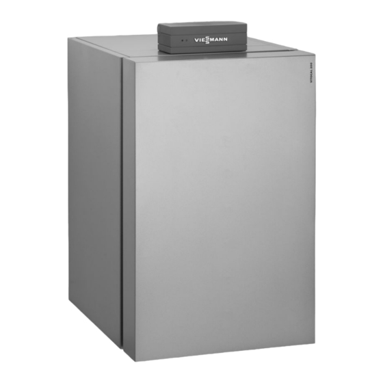
Vitocal 200-G
Type BWC 201.A06 to A17, 6 to 17 kW
Brine/water heat pump with electric drive, 400 V~
Type BWC-M 201.A06 to A10, 6 to 10 kW
Brine/water heat pump with electric drive, 230 V~
For applicability, see the last page
VITOCAL 200-G
Please keep safe.
5546 220 GB
6/2014
Advertisement
Chapters
Table of Contents

Subscribe to Our Youtube Channel
Related Manuals for Viessmann VITOCAL 200-G


Summary of Contents for Viessmann VITOCAL 200-G
- Page 1 VIESMANN Installation and service instructions for contractors Vitocal 200-G Type BWC 201.A06 to A17, 6 to 17 kW Brine/water heat pump with electric drive, 400 V~ Type BWC-M 201.A06 to A10, 6 to 10 kW Brine/water heat pump with electric drive, 230 V~...
- Page 2 Safety instructions Safety instructions Please follow these safety instructions closely to prevent accidents and mate- rial losses. Safety instructions explained ■ Codes of practice of the relevant trade associations. Danger ■ All current safety regulations as This symbol warns against the defined by DIN, EN, DVGW, VDE and risk of injury.
- Page 3 Repairing components that fulfil a safety function can compromise the safe operation of your sys- tem. Defective components must be replaced with genuine Viessmann spare parts. Auxiliary components, spare and wearing parts Please note Spare and wearing parts that have not been tested together with the system can compromise its function.
-
Page 4: Table Of Contents
Index Index Installation instructions Preparing for installation Intended use......................Requirements for on-site connections..............Requirements for siting..................Installation sequence Siting the heat pump.................... 11 Making the hydraulic connections................ 14 Electrical connections................... 16 Power supply......................33 Make connections at terminals X3.8/X3.9............44 Closing the heat pump.................. - Page 5 Index Index (cont.) Specification....................... 104 Appendix Commissioning order................... 109 Certificates Declaration of conformity..................110 Keyword index....................111...
-
Page 6: Preparing For Installation
Preparing for installation Intended use The appliance is only intended to be Commercial or industrial usage for a pur- installed and operated in sealed unven- pose other than central heating/cooling ted heating systems that comply with or DHW heating shall be deemed inap- EN 12828, with due attention paid to the propriate. -
Page 7: Requirements For On-Site Connections
Preparing for installation Requirements for on-site connections 230 V < 42 V Heating flow DHW cylinder flow Secondary circuit return (heating return and DHW cylinder return) Primary circuit return (heat pump brine outlet) Primary circuit flow (heat pump brine inlet) Install hydraulic connections on site stress-free. -
Page 8: Requirements For Siting
Preparing for installation Requirements for on-site connections (cont.) Cable lengths in the heat pump plus wall clearance Heat pump control unit power supply (230 V~) 1.0 m Compressor power supply (400 V~/230 V~) 1.0 m Additional connecting cables 1.0 m Recommended power cables Power cable Output stage... - Page 9 Preparing for installation Requirements for siting (cont.) Installation room requirements Please note Total weight The installation room must be dry Type Weight in kg and free from the risk of frost. BWC (400 V appliances) Ensure ambient temperatures 201.A06 between 0 and 35 °C. 201.A08 201.A10 Please note...
- Page 10 Preparing for installation Requirements for siting (cont.) Minimum clearances ≥ 400 A Dimension subject to on-site instal- lation and site conditions B ≥ 100 mm...
-
Page 11: Installation Sequence
Installation sequence Siting the heat pump Removing the transport brackets and levelling the heat pump... - Page 12 Installation sequence Siting the heat pump (cont.) Please note 2. Position and level the heat pump hor- Operating the appliance with- izontally as described on page 8. out first removing the trans- port brackets may cause vibrations and excessive noise. Remove the transport brack- ets.
- Page 13 Installation sequence Siting the heat pump (cont.) Removing the top panel...
-
Page 14: Making The Hydraulic Connections
Note Ensure frost protection down to –19 °C. Viessmann heat transfer medium is a ready-mixed ethylene glycol-based medium. It contains inhibitors for cor- rosion protection. The heat transfer medium can be used at temperatures down to –19 °C. - Page 15 Installation sequence Making the hydraulic connections (cont.) Note For diaphragm grommets, see page 46. Connecting the secondary circuit 1. Equip the secondary circuit on site 3. Fill and vent secondary circuit. with an expansion vessel and safety assembly (to DIN 4757). 4.
-
Page 16: Electrical Connections
Installation sequence Electrical connections Installing the programming unit... - Page 17 Installation sequence Electrical connections (cont.) [XÖ Routing cables to the wiring chamber Danger Danger Damaged cable insulation can Incorrect wiring can lead to seri- cause injury and damage to the ous injury from electrical current appliance. and result in appliance damage. Route cables so that they cannot Observe the following points touch very hot, vibrating or sharp-...
- Page 18 Installation sequence Electrical connections (cont.) ■ Route LV cables < 42 V separately This ensures that, in the event of a fault from cables > 42 V/230 V~/400 V~. (e.g. when detaching a wire), the wires ■ Strip the insulation from the cables as cannot drift into the adjacent voltage close to the terminals as possible, and area.
- Page 19 Installation sequence Electrical connections (cont.) Note Route LV leads and 230 V~ cables as far apart as possible. Overview of the electrical connections in the heat pump control unit A Luster terminals: See page 28. C Expansion PCB on main PCB: See F1 Fuse 6.3 A (slow) page 25.
- Page 20 Installation sequence Electrical connections (cont.) Main PCB Information regarding connection Set the required parameters during com- values missioning: See from page 51. ■ The specified output is the recommen- ded connected load. ■ The total output of all components con- nected directly to the heat pump con- trol unit (e.g.
- Page 21 Installation sequence Electrical connections (cont.) Function components 230 V~ Plug sYA Terminals Function Explanation 211.2 Secondary pump ■ In systems without a heating water buf- fer cylinder, no other heating circuit pump is required (see terminal 212.2). ■ Connect a temperature limiter to restrict the maximum temperature for under- floor heating circuits (if installed) in ser- ies.
- Page 22 Installation sequence Electrical connections (cont.) Plug sYA Terminals Function Explanation 211.4 Connection values ■ Circulation pump for cyl- ■ Output: 130 W inder heating ■ Voltage: 230 V~ ■ Max. switching current: 4(2) A ■ Cylinder loading pump Note The circulation pump for cylinder heating is connected at the factory.
- Page 23 Installation sequence Electrical connections (cont.) Plug sYS Terminals Function Explanation 212.3 DHW circulation pump Connection values ■ Output: 50 W ■ Voltage: 230 V~ ■ Max. switching current: 4(2) A 212.4 3-way diverter valve for Connection values heating water buffer cylin- ■...
- Page 24 Installation sequence Electrical connections (cont.) Connection A to Circulation pump C control unit Heating circuit without mixer A1/HC1 ■ Without heating water buffer cylin- 211.2 Secondary pump ■ With heating water buffer cylinder 212.2 Heating circuit pump A1/ Heating circuit with mixer M2/HC2 225.1 Heating circuit pump M2/HC2 Connecting the temperature limiter,...
- Page 25 Installation sequence Electrical connections (cont.) Expansion PCB on main PCB Information regarding the connection Set the required parameters during com- values missioning: See from page 51. ■ The specified output is the recommen- ded connected load. ■ The total output of all components con- nected directly to the heat pump con- trol unit (e.g.
- Page 26 Installation sequence Electrical connections (cont.) Plug sXS Terminals Function Explanation 222.3 Control of external heat Floating contact 222.4 generators and 1 high limit safety cut-out each (on site, Connection values (contact rating): max. 70 °C), to switch off or ■ Voltage: 230 V~ switch between the follow- (not suitable for safety LV) ing components:...
- Page 27 Installation sequence Electrical connections (cont.) Plug sXF Terminals Function Explanation 224.4 Control of instantaneous Connection values heating water heater, ■ Output: 10 W stage 2 ■ Voltage: 230 V~ ■ Max. switching current: 4(2) A 224.7 Connection values Circulation pump for DHW ■...
- Page 28 Installation sequence Electrical connections (cont.) Immersion heater (230 V~, on site) 224.7 X2.N A Immersion heater, power supply B Terminals of the heat pump control 1/N/PE 230 V/50 Hz unit Luster terminals Set the required parameters during com- missioning: See from page 51. Signal and safety connections Terminals Function...
- Page 29 Installation sequence Electrical connections (cont.) Terminals Function Explanation X3.3 Jumper Never remove X3.4 X3.6 Power-OFF Requires zero volt N/C contact: X3.7 ■ Closed: No power-OFF (safety chain has continuity) ■ Open: Power-OFF enabled ■ Breaking capacity 230 V~, 0.15 A No jumper should be installed if a power- OFF contact is connected.
- Page 30 Installation sequence Electrical connections (cont.) Controller and sensor PCB Set the required parameters during com- Note missioning: See from page 51. Flow temperature sensor for heating circuit with mixer M2/HC2: The flow temperature sensor for one heating cir- cuit with mixer M2/HC2 is connected to the mixer extension kit (accessories).
- Page 31 Modbus 1 — Viessmann appliances, e.g. ventilation unit Vitovent 300-F Note If other Viessmann appliances are to be connected to Modbus 1, plug in the Modbus distributor (accessories): See installation instructions "Modbus distributor". Connection, LON communication module (accessories): — See installation instructions "LON communication mod- ule".
- Page 32 Installation sequence Electrical connections (cont.) Swimming pool heating Note ■ Swimming pool heating is controlled via extension EA1 with KM BUS. ■ Make connections to extension EA1 only according to the following dia- gram. ■ A filter circuit pump cannot be control- led via the heat pump control unit.
-
Page 33: Power Supply
Installation sequence Electrical connections (cont.) D Fuses and contactor for circulation G Circulation pump for swimming pool pump for swimming pool heating heating (accessory) H Thermostat for swimming pool tem- (accessories) E Jumper perature control (floating contact: 230 V~, 0.1 A, accessories) F 3-way diverter valve for "Swimming K Connection on controller and sensor pool"... - Page 34 Installation sequence Power supply (cont.) Danger ■ The heat pump control unit/PCB Incorrect core allocation can must be supplied with power without result in serious injury and dam- being interrupted by the power supply age to the appliance. utility. Tariffs subject to possible shut- Never interchange cores "L"...
- Page 35 Installation sequence Power supply (cont.) Heat pump control unit power supply 230 V~ ■ Recommended power cable: 1 / N / PE 3 x 1.5 mm 230 V / 50 Hz ■ Recommended power cable with power-OFF periods for compressor/ F1 6.3 A slow instantaneous heating water heater: 5 x 1.5 mm...
- Page 36 Installation sequence Power supply (cont.) Recommended power cables for 230 V appliances: Type BWC-M 201.A Power cable — — 3 x 4.0 mm 3 x 4.0 mm 3 x 4.0 mm Max. cable length 40 m 32 m 26 m —...
- Page 37 Installation sequence Power supply (cont.) Connection type BWC 201.A (400 V~) X3.7 X3.6 Diagram excluding fuses and RCDs A Heat pump control unit F Backup fuse ripple control receiver B Instantaneous heating water heater G Ripple control receiver (contact (accessory) open: power-OFF active) TNC sys- C Compressor tem feed...
- Page 38 Installation sequence Power supply (cont.) Connection type BWC-M 201.A (230 V~) X3.7 X3.6 Diagram excluding fuses and RCDs A Heat pump control unit F Backup fuse ripple control receiver B Instantaneous heating water heater G Ripple control receiver (contact (accessory) open: power-OFF active) TNC sys- C Compressor tem feed...
- Page 39 Installation sequence Power supply (cont.) Connection type BWC 201.A (400 V~) X3.7 X3.6 Diagram excluding fuses and RCDs A Heat pump control unit F Backup fuse ripple control receiver B Instantaneous heating water heater G Ripple control receiver (contact (accessory) open: power-OFF enabled) with C Compressor backup fuse...
- Page 40 Installation sequence Power supply (cont.) Connection type BWC-M 201.A (230 V~) X3.7 X3.6 Diagram excluding fuses and RCDs A Heat pump control unit F Backup fuse ripple control receiver B Instantaneous heating water heater G Ripple control receiver (contact (accessory) open: power-OFF enabled) with C Compressor backup fuse...
- Page 41 Installation sequence Power supply (cont.) Mains power supply in conjunction with on-site power consump- tion Without power-OFF E1E2 D /D L1 L1 L2 L2 L3 L3 A Heat pump F Terminal B Additional consumers (of power G Double-tariff meter (for special tariff generated on site) in the house- for heat pump) hold...
- Page 42 Installation sequence Power supply (cont.) H Bi-directional meter (for PV systems L Isolator for the domestic power sup- to consume power on site): ply connection (distribution panel) Energy taken from power supply M Distribution panel utility and energy fed into power N Domestic distribution box supply utility K Meter with reverse block:...
- Page 43 Installation sequence Power supply (cont.) Version 1 A Over/undervoltage in % B Phase asymmetry in % <>U <>U C Switching delay in s D Contact used in safety chain (N/O) E ON/OFF indicator ("Rel") F Fault display phase failure/phase sequence ("Ph") G Fault display asymmetry ("Asy") H Fault display over/undervoltage ("<>U")
-
Page 44: Make Connections At Terminals X3.8/X3.9
Installation sequence Power supply (cont.) Version 2 N 11 21 LEDs explained A Voltage "U": Illuminates green if voltage is L1 L2 L3 applied. B Relay "R": Illuminates yellow if the phase sequence is correct. Does not illuminate if the phase sequence is incorrect. -
Page 45: Closing The Heat Pump
Installation sequence Closing the heat pump Please note Danger Leaking hydraulic connections If system components are not lead to appliance damage. earthed, serious injury from elec- ■ Check internal hydraulic con- tric current can result if an elec- nections for leaks. trical fault occurs. -
Page 46: Check The Diaphragm Grommets
Installation sequence Check the diaphragm grommets Please note Seal the appliance so it is sound- proof and diffusion-proof. With the hose outlets, ensure dia- phragm grommets A are seated correctly. Seal diaphragm grom- mets A with adhesive tape if necessary. -
Page 47: Commissioning, Inspection, Maintenance
Commissioning, inspection, maintenance Steps - commissioning, inspection and maintenance For further information regarding the individual steps, see the page indicated Commissioning steps Inspection steps Maintenance steps Page • • • 1. Opening the heat pump............ 48 • 2. Writing reports..............48 •... -
Page 48: Further Details Regarding The Individual Steps
Commissioning, inspection, maintenance Further details regarding the individual steps Opening the heat pump Danger Please note Contact with 'live' components Wait at least 30 min between the can lead to serious injury from installation and commissioning of electric current. the appliance to prevent equip- ■... -
Page 49: Checking The Refrigerant Circuit For Leaks
Viessmann heat transfer medium and vent. Note Ensure frost protection down to –19 °C. Viessmann heat transfer medium is a ready-mixed ethylene glycol-based medium. It contains inhibitors for cor- rosion protection. The heat transfer medium can be used at temperatures down to –19 °C. -
Page 50: Checking The Expansion Vessels And Primary Circuit/ Heating Circuit Pressure
Commissioning, inspection, maintenance Further details regarding the individual steps (cont.) ■ Flush the heating system thoroughly Please note before filling. Avoid appliance damage. ■ Only fill with water of potable quality. ■ Check the secondary circuit ■ Soften fill water with a water hardness flow and return connections to the heat pump for tight- above 16.8 °dH (3.0 mol/m... -
Page 51: Commissioning The System
Commissioning, inspection, maintenance Further details regarding the individual steps (cont.) Commissioning the system Commissioning (configuration, parame- Note ter settings and function check) can be The type and extent of the parameters carried out with or without the commis- depend on the appliance type, on the sioning wizard (see following chapter selected system scheme and the acces- and service instructions for the heat... - Page 52 Commissioning, inspection, maintenance Further details regarding the individual steps (cont.) Language Date Date/time Time Start commissioning? Coding Parameter group Parameter level 1 select Sensor values Temperature sensors display Signal inputs Signal inputs display Actuator test Actuator test carry out Subscriber check Subscriber check (LON) carry out Function check...
- Page 53 Commissioning, inspection, maintenance Further details regarding the individual steps (cont.) Commissioning without the commissioning assistant Enabling the service menu Service menu: 1. Press OK + å simultaneously for The service menu can be enabled from approx. 4 s any menu. 2.
- Page 54 Commissioning, inspection, maintenance Further details regarding the individual steps (cont.) Component System scheme DHW cylinder — — — — Immersion heater: See page 58. — — — — Heating water buffer cylinder — — External heat generator: See page 58. —...
- Page 55 Commissioning, inspection, maintenance Further details regarding the individual steps (cont.) Pumps and other components Pump/component Parameter Setting Heating circuit pump "System definition" Ó ■ With heating circuit A1/ HC1 (for heating circuit "System scheme 7000" without mixer) ■ With heating circuit M2/ HC2 (for heating circuit with mixer) DHW circulation pump...
- Page 56 Commissioning, inspection, maintenance Further details regarding the individual steps (cont.) Pump/component Parameter Setting Remote control for heat- "Heating circuit 1" Ó "1" ing/cooling circuit "Remote control 2003" Note Set heating circuit allocation "Heating circuit 2" Ó on the Vitotrol. "Remote control 3003" See "Vitotrol"...
- Page 57 Commissioning, inspection, maintenance Further details regarding the individual steps (cont.) External functions External functions Parameter Setting External demand "Internal hydraulics", if ap- Set flow temperature plicable Ó for external demand "Flow temperature for ex- ternal demand 730C" External starting of the com- "System definition"...
- Page 58 Commissioning, inspection, maintenance Further details regarding the individual steps (cont.) Immersion heater Immersion heater parameters Setting "DHW" Ó "1" "Enable electric heaters for DHW heating 6015" "DHW" Ó "1" "Enable booster heaters for DHW heating 6014" External heat source External heat source parameters Setting "External heat source"...
- Page 59 Commissioning, inspection, maintenance Further details regarding the individual steps (cont.) Swimming pool water heating Parameters for swimming pool heating Setting "System definition" Ó "1" "External extension 7010" "System definition" Ó "1" "Swimming pool 7008" Solar Parameters for solar thermal system in con- Setting junction with solar control module, type SM1 "Solar"...
- Page 60 Commissioning, inspection, maintenance Further details regarding the individual steps (cont.) Ice store/solar air absorber Parameters for ice store and solar air absorb- Setting "System definition" Ó "1" "Select primary source 7030" "System definition" Ó "2" "External extension 7010" "Solar" Ó "2"...
-
Page 61: Instructing The System User
Commissioning, inspection, maintenance Further details regarding the individual steps (cont.) Electricity meter parameters Setting Extended menu: Specify the temperature differen- "PV ctrl strategy" tial to the selected set value for the chosen function. "Photovoltaics" Ó ■ "Raise set DHW cylinder temperature PV "0"... -
Page 62: Troubleshooting
Troubleshooting Repairs Overview of wiring chamber Type BWC 201.A (400 V appliances) - Page 63 Troubleshooting Repairs (cont.) Type BWC-M 201.A (230 V appliances) A Programming unit H Phase monitor (accessory for type BWC 201.B) B Controller and sensor PCB K Start capacitor C Main PCB L Run capacitor D Expansion PCB on the main PCB M Compressor contactor E Compressor mains terminals N Thermal relay...
- Page 64 Troubleshooting Repairs (cont.) Opening the casing door...
- Page 65 Troubleshooting Repairs (cont.) Overview of internal components...
- Page 66 Troubleshooting Repairs (cont.)
- Page 67 Troubleshooting Repairs (cont.) Heating flow G Primary pump I Thermal expansion valve TEV J Compressor DHW cylinder flow K Flow temperature sensor, secon- dary circuit Secondary circuit return (heat- L Return temperature sensor, secon- ing return and DHW cylinder re- dary circuit turn) M Drain valve, secondary side...
- Page 68 (PTC) ■ Flow temperature sensor, secondary circuit (F8) ■ Return temperature sensor, secondary circuit (F9) ■ Sensors in the refrigerant circuit Viessmann NTC 10 kΩ (marked blue) Other sensors Outside temperature sensor 10 30 50 70 90 110 -20 -10 10 20 30 Temperature in °C...
- Page 69 Troubleshooting Repairs (cont.) Viessmann Pt500A (marked green) 140 180 Temperature in °C Checking the fuses Position of the fuses: See page 19. Danger Removing the fuse does not ■ Fuse F1 is located on the mains ter- switch the power circuit to zero minal of the heat pump control unit.
- Page 70 Troubleshooting Repairs (cont.) Condensation and moisture in the heat pump module Possible causes: ■ Hose outlets in diaphragm grommets not watertight: See page 46. ■ Casing door not tightly sealed: See page 64. ■ Outer panels not diffusion-proof...
-
Page 71: Parts Lists, Type Bwc 201.A (400 V Appliances)
Parts lists, type BWC 201.A (400 V appliances) Overview of the assemblies A Type plate C Electrical equipment assembly B Casing assembly... -
Page 72: Parts Not Shown
Parts lists, type BWC 201.A (400 V appliances) Overview of the assemblies (cont.) D Heat pump module assembly E Hydraulic assembly Parts not shown Type BWC 201.A (400 V appliances) Pos. Component Part no. 0005 Small parts, casing 7835116 0006 Touch-up paint stick, Vitosilver 7819546 0007... - Page 73 Parts lists, type BWC 201.A (400 V appliances) Casing (cont.) Pos. Component Part no. 0017 Front panel 7835142 0018 Shield 7840706 0019 Vitocal 200 logo 7839931 0020 Diaphragm grommet 7826672 0022 Location stud M5 7814668...
- Page 74 Parts lists, type BWC 201.A (400 V appliances) Casing (cont.) 0005 0007 0020 0016 0015 0009 0014 0008 0002 0015 0018 0003 0014 0022 0002 0010 0003 0001 0019 0001 0001 0001 0015 0006 0013 0017 0019 0012 0011 0004...
-
Page 75: Electrical Equipment
Parts lists, type BWC 201.A (400 V appliances) Electrical equipment Type BWC 201.A (400 V appliances) Pos. Component Serial no. (see type plate) 7514482 7514483 7514484 7514485 7514486 Part no. 0001 Programming unit, 7841889 7841889 7841889 7841889 7841889 Vitotronic 200 heat pump control unit 0002 Controller and sen-... - Page 76 Parts lists, type BWC 201.A (400 V appliances) Electrical equipment (cont.) Pos. Component Serial no. (see type plate) 7514482 7514483 7514484 7514485 7514486 Part no. 0039 Mating plug for main 7832896 7832896 7832896 7832896 7832896 PCB (set) 0040 Mating plug for ex- 7832897 7832897 7832897 7832897 7832897 pansion PCB (set)
- Page 77 Parts lists, type BWC 201.A (400 V appliances) Electrical equipment (cont.) 0040 0042 0007 0038 0041 0006 0002 0039 0030 0001 0004 0003 0005 0012 0024 0027 0025 0027 0025 0009 0035 0036 0022 0047 0043 0046 0050 0045 0037 0051...
-
Page 78: Heat Pump Module
Parts lists, type BWC 201.A (400 V appliances) Heat pump module Type BWC 201.A (400 V appliances) Pos. Component Serial no. (see type plate) 7514482 7514483 7514484 7514485 7514486 Part no. 0001 Compressor 7832579 7830715 7830716 7835058 7835007 0002 Evaporator 7835003 7835045 7835051 7835055 7835135 0003... - Page 79 Parts lists, type BWC 201.A (400 V appliances) Heat pump module (cont.) Pos. Component Serial no. (see type plate) 7514482 7514483 7514484 7514485 7514486 Part no. 0025 Retainer, tempera- 7832740 7832740 7832740 7832740 7832740 ture sensor 0026 Thermal circuit 7825034 7825034 7825034 7825034 7825034 breaker (Klixon) 0027...
- Page 80 Parts lists, type BWC 201.A (400 V appliances) Heat pump module (cont.) 0002 0022 0009 0013 0006 0015 0020 0027 0021 0023 0025 0028 0008 0022 0009 0003 0013 0026 0019 0014 0015 0005 0001 0004 0018 0011 0012 0016 0024 0017 0010...
-
Page 81: Hydraulics
Parts lists, type BWC 201.A (400 V appliances) Hydraulics Type BWC 201.A (400 V appliances) Pos. Component Serial no. (see type plate) 7514482 7514483 7514484 7514485 7514486 Part no. 0001 Gasket 7814728 7814728 7814728 7814728 7814728 A 35 x 45 x 2.0 mm 0002 Spring clip for tem- 7836480 7836480 7836480 7836480... - Page 82 Parts lists, type BWC 201.A (400 V appliances) Hydraulics (cont.) Pos. Component Serial no. (see type plate) 7514482 7514483 7514484 7514485 7514486 Part no. 0019 Threaded pipe clip 7832672 7832672 7832672 7832672 7832672 7 31 to 35 mm, M8, with EPDM insert 0020 Threaded pipe clip 7830464 7830464 7830464 7830464...
- Page 83 Parts lists, type BWC 201.A (400 V appliances) Hydraulics (cont.) 0012 0023 0005 0004 0002 0005 0001 0014 0015 0009 0001 0005 0005 0006 0007 0001 0001 0018 0013 0013 0001 0001 0001 0001 0021 0016 0005 0001 0017 0001 0011 0007 0021...
-
Page 84: Parts Lists, Type Bwc-M 201.A (230 V Appliances)
Parts lists, type BWC-M 201.A (230 V appliances) Overview of the assemblies A Type plate C Electrical equipment assembly B Casing assembly... -
Page 85: Parts Not Shown
Parts lists, type BWC-M 201.A (230 V appliances) Overview of the assemblies (cont.) D Heat pump module assembly E Hydraulic assembly Parts not shown Type BWC-M 201.A (230 V appliances) Pos. Component Part no. 0005 Small parts, casing 7835116 0006 Touch-up paint stick, Vitosilver 7819546 0007... - Page 86 Parts lists, type BWC-M 201.A (230 V appliances) Casing (cont.) Pos. Component Part no. 0017 Front panel 7835142 0018 Shield 7840706 0019 Vitocal 200 logo 7839931 0020 Diaphragm grommet 7826672 0022 Location stud M5 7814668...
- Page 87 Parts lists, type BWC-M 201.A (230 V appliances) Casing (cont.) 0005 0007 0020 0016 0015 0009 0014 0008 0002 0015 0018 0003 0014 0022 0002 0010 0003 0001 0019 0001 0001 0001 0015 0006 0013 0017 0019 0012 0011 0004...
-
Page 88: Electrical Equipment
Parts lists, type BWC-M 201.A (230 V appliances) Electrical equipment Type BWC-M 201.A (230 V appliances) Pos. Component Serial no. (see type plate) 7514487 7514488 7514489 Part no. 0001 Programming unit, Vitotronic 200 heat 7841889 7841889 7841889 pump control unit 0002 Controller and sensor PCB with cover 7840551 7840551... - Page 89 Parts lists, type BWC-M 201.A (230 V appliances) Electrical equipment (cont.) 0042 0007 0040 0038 0041 0006 0002 0039 0030 0004 0001 0003 0005 0012 0009 0052 0053 0027 0035 0025 0036 0024 0022 0025 0027 0043 0047 0046 0050 0045 0037 0051...
-
Page 90: Heat Pump Module
Parts lists, type BWC-M 201.A (230 V appliances) Heat pump module Type BWC-M 201.A (230 V appliances) Pos. Component Serial no. (see type plate) 7514487 7514488 7514489 Part no. 0001 Compressor 7832582 7832581 7830719 0002 Evaporator 7835003 7835045 7835051 0003 Condenser 7835004 7835122 7835049... - Page 91 Parts lists, type BWC-M 201.A (230 V appliances) Heat pump module (cont.) 0002 0022 0009 0013 0006 0015 0020 0027 0021 0023 0025 0028 0008 0022 0009 0003 0013 0026 0019 0014 0015 0005 0001 0004 0018 0011 0012 0016 0024 0017 0010...
-
Page 92: Hydraulics
Parts lists, type BWC-M 201.A (230 V appliances) Hydraulics Type BWC-M 201.A (230 V appliances) Pos. Component Serial no. (see type plate) 7514487 7514488 7514489 Part no. 0001 Gasket A 35 x 45 x 2.0 mm 7814728 7814728 7814728 0002 Spring clip for temperature sensor 7836480 7836480 7836480... - Page 93 Parts lists, type BWC-M 201.A (230 V appliances) Hydraulics (cont.) 0012 0023 0005 0004 0002 0005 0001 0014 0015 0009 0001 0005 0005 0006 0007 0001 0001 0018 0013 0013 0001 0001 0001 0001 0021 0016 0005 0001 0017 0001 0011 0007 0021...
-
Page 94: Commissioning/Service Reports
Commissioning/service reports Hydraulic parameters report Setting and test values Setpoint Commis- Mainte- sioning nance/Serv- Frost protection (brine medi- °C –19 Testing the external heating circuit pumps Circulation pump type Circulation pump stage Overflow valve setting Commissioning, primary circuit Primary circuit flow tempera- °C ture ("Diagnosis"... -
Page 95: Control Parameters Report
Commissioning/service reports Control parameters report Parameter description "Vitotronic 200" service instruc- tions System definition Parameter Code Delivered Commis- Mainte- condition sioning nance/ Service "System scheme" (see chapter 7000 "Overview of possible system schemes") "Temperature differential for 7003 40 (≙ 4 K) calculating the heating limit"... - Page 96 Commissioning/service reports Control parameters report (cont.) Parameter Code Delivered Commis- Mainte- condition sioning nance/ Service "Last calendar week for sum- 7036 mer mode" "Absorber circuit monitoring" 7037 "Temperature sensor for dual 7038 mode operation" Compressor Parameter Code Delivered Commis- Mainte- condition sioning nance/...
- Page 97 Commissioning/service reports Control parameters report (cont.) Parameter Code Delivered Commis- Mainte- condition sioning nance/ Service "Set DHW temperature" 6000 500 (≙ 50 °C) "Min. DHW temperature" 6005 100 (≙ 10 °C) "Max. DHW temperature" 6006 600 (≙ 60 °C) "Hysteresis DHW temperature 6007 50 (≙...
- Page 98 Commissioning/service reports Control parameters report (cont.) Electric booster heater Parameter Code Delivered Commis- Mainte- condition sioning nance/ Service "Enable instantaneous heat- 7900 ing water heater" "Enable electric heaters for 7901 DHW heating" "Enable instant. heating water 7902 heater for central heating" "Max.
- Page 99 Commissioning/service reports Control parameters report (cont.) Heating water buffer cylinder Parameter Code Delivered Commis- Mainte- condition sioning nance/ Service "Enable buffer cylinder/low 7200 loss header" "Temp in operating status 7202 500 (≙ 50 °C) fixed value for buffer cyl" "Hysteresis temperature heat- 7203 50 (≙...
- Page 100 Commissioning/service reports Control parameters report (cont.) Heating circuit 2 Parameter Code Delivered Commis- Mainte- condition sioning nance/ Service "Standard room temperature" 3000 200 (≙ 20 °C) "Reduced room temperature" 3001 160 (≙ 16 °C) "Remote control" 3003 "Heating curve level" 3006 0 (≙...
- Page 101 Commissioning/service reports Control parameters report (cont.) Ventilation Parameter Code Delivered Commis- Mainte- condition sioning nance/ Service "Vitovent enable" 7D00 "Enable preheater bank elec- 7D01 tric" "Enable reheater bank hy- 7D02 draulic" "Enable humidity sensor" 7D05 "Enable CO2 sensor" 7D06 "Set extract air temperature" 7D08 200 (≙...
- Page 102 Commissioning/service reports Control parameters report (cont.) Photovoltaics Parameter Code Delivered Commis- Mainte- condition sioning nance/ Service "Enable own energy con- 7E00 sumption PV" "Prop. of external current" 7E02 10 (≙ 10 %) "Threshold for electrical pow- 7E04 0 (≙ 0 W) er"...
- Page 103 Commissioning/service reports Control parameters report (cont.) Communication Parameter Code Delivered Commis- Mainte- condition sioning nance/ Service "Number of heat pump in cas- 7707 cade" "Enable LON communication 7710 module" "LON subscriber number" 7777 "LON fault manager" 7779 "LON system number" 7798 "Interval for data transfer via 779C...
-
Page 104: Specification
Specification Specification 400 V appliances Type BWC 201.A Output data to EN 14511 (B0/W35, 5 K spread) Rated heating output 5.76 7.63 9.74 13.00 17.20 Cooling capacity 4.51 6.01 7.69 10.34 13.66 Power consumption 1.34 1.74 2.21 2.86 3.81 Coefficient of performance ε 4.30 4.40 4.41... - Page 105 Specification Specification (cont.) Type BWC 201.A Electrical values, heat pump Rated voltage, compressor 3/N/PE 400 V/50 Hz Rated current, compressor 10.0 15.0 Starting current, compres- 25.0 14.0 20.0 22.0 25.0 (with starting current limiter, not for type BWC 201.A06) Starting current, compressor 26.0 35.0 48.0...
- Page 106 Specification Specification (cont.) Type BWC 201.A Dimensions Total length Total width Total height (programming 1155 1155 1155 1155 1155 unit pivoted up) Weight Connections Primary circuit flow/return 1½ 1½ 1½ 1½ 1½ Secondary circuit flow/re- 1½ 1½ 1½ 1½ 1½ turn Sound power level (tested with reference to EN 12102/...
- Page 107 Specification Specification (cont.) Type BWC-M 201.A Brine (primary circuit) Contents Minimum flow rate (5 K 1100 1420 spread) Residual head (at minimum mbar flow rate) Max. flow temperature °C Min. flow temperature °C –5 –5 –5 Heating water (secondary circuit) Contents Minimum flow rate (10 K spread)
- Page 108 Specification Specification (cont.) Type BWC-M 201.A Electrical values, control unit Rated voltage 1/N/PE 230 V/50 Hz MCB/fuse protection B16A Fuses 2 x 6.3 A H (slow)/250 V Max. power consumption 1000 1000 1000 Power consumption in opera- tion Refrigerant circuit Refrigerant R410A R410A...
-
Page 109: Appendix
Components for ventilation fully installed (optional) Components for PV system fully installed (optional) Preferred appointment: Date Time Date Time The work that is requested to be carried out by Viessmann will be billed in accordance with the latest Viessmann pricelist. Place/date Signature... -
Page 110: Certificates
Declaration of conformity We, Viessmann Werke GmbH & Co KG, D-35107 Allendorf, declare as sole respon- sible body that the product Vitocal 200-G, type BWC 201.A/BWC-M 201.A, incl. heat pump control unit Vitotronic 200, type WO1C, complies with the following stand-... -
Page 111: Keyword Index
Keyword index Keyword index Compressor......67, 78, 90 Adjustable feet........9 Compressor contactor......63 Air vent valve, secondary side...67 Condensation in the heat pump mod- Aligning the appliance......9 ule............70 Ambient temperatures......9 Condenser......67, 78, 90 Appliance fuse........69 Connected load........20 Appliance too noisy......69 Connecting cables......18 Assemblies........71, 84 Connections.........7 Assembly... - Page 112 Keyword index Keyword index (cont.) Electrical connection......16 Fuse F3..........69 – Controller and sensor PCB.....30 Fuses........19, 75, 88 – Expansion PCB......25 – Checking.........69 – Luster terminals......28 – Main PCB........20 Electrical connections......16 Heating circuit pump....22, 55 – Cables, routing.......17 Heating flow........7, 67 –...
- Page 113 Keyword index Keyword index (cont.) Main PCB.......19, 20, 63 Parameter Mains isolator......39, 40, 48 – Immersion heater......58 Mains terminals......63, 75, 88 Parameters Maintenance........48 – Cooling function......59 Making the hydraulic connections..14 – Electric booster heater....58 Maximum temperature limiter....23 – External extension......56 MCB/fuse protection......35 –...
- Page 114 Keyword index Keyword index (cont.) Primary circuit pressure switch..44 Schrader valve Primary pump........67 – High pressure.........67 Programming unit.......63 – Low pressure........67 – Installing.........16 Seal rings, replacing......50 Pumps..........55, 65 Secondary circuit – Connecting........15 – Filling..........50 Radio clock receiver......30 – Filling and venting......49 Refrigerant circuit sensors....68 –...
- Page 115 Keyword index Keyword index (cont.) Temperature limiter......15, 23 Underfloor heating......23 Temperature sensor Underfloor heating circuit.....15, 23 – Curve, type Pt500A......69 Temperature Sensor – Curve, type NTC 10 kΩ....68 Ventilation..........61 Temperature sensors......30 Venting Terminating service......53 – Primary side........49 Terminator, Modbus......31 – Secondary side.......49 Thermal expansion valve..67, 78, 90 Vitocom..........56 Thermal relay........63...
- Page 116 Serial No.: 7514482 7514483 7514484 7514485 7514486 7514487 7514488 7514489 Viessmann Werke GmbH&Co KG Viessmann Limited D-35107 Allendorf Hortonwood 30, Telford Telephone: +49 6452 70-0 Shropshire, TF1 7YP, GB Fax: +49 6452 70-2780 Telephone: +44 1952 675000 www.viessmann.com Fax: +44 1952 675040...
Need help?
Do you have a question about the VITOCAL 200-G and is the answer not in the manual?
Questions and answers