Table of Contents
Advertisement
Quick Links
VIESMANN
Technical guide
VITOCAL 200-A
Type AWO(-M) 201.A
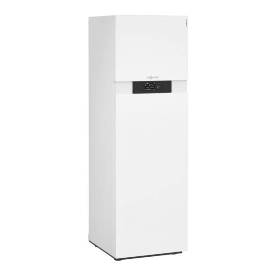
Air/water heat pump with electric drive in monoblock design
with outdoor and indoor unit
For central heating and DHW heating in heating systems
■
Indoor unit with Vitotronic 200 heat pump controller, high
■
efficiency circulation pump for the secondary circuit, 3-way
diverter valve and safety assembly
Type AWO(-M)-E 201.A
Equipment level as per type AWO(-M) 201.A, additionally
with integral instantaneous heating water heater
Type AWO(-M)-E-AC 201.A
Equipment level as per type AWO(-M) 201.A, additionally
with integral instantaneous heating water heater and active
cooling function
5831388 GB
5/2019
Air/water heat pumps with indoor and outdoor units
VITOCAL 222-A
Type AWOT(-M)-E 221.A
Heat pump compact appliance with electric drive in mono-
block design with outdoor and indoor unit
For central heating and DHW heating in heating systems
■
Indoor unit with Vitotronic 200 heat pump control unit, 220 l
■
capacity integral DHW cylinder, high efficiency circulation
pump for the secondary circuit, integral instantaneous heat-
ing water heater, 3-way diverter valve and safety assembly
Type AWOT(-M)-E-AC 221.A
Equipment level as per type AWOT(-M)-E 221.A, additionally
with active cooling function
VITOCAL
Monoblock version, 2.4 to 14.7 kW
Advertisement
Table of Contents

Related Manuals for Viessmann VITOCAL Series


Summary of Contents for Viessmann VITOCAL Series
- Page 1 VIESMANN VITOCAL Air/water heat pumps with indoor and outdoor units Monoblock version, 2.4 to 14.7 kW Technical guide VITOCAL 200-A VITOCAL 222-A Type AWO(-M) 201.A Type AWOT(-M)-E 221.A Air/water heat pump with electric drive in monoblock design Heat pump compact appliance with electric drive in mono- with outdoor and indoor unit block design with outdoor and indoor unit For central heating and DHW heating in heating systems...
-
Page 2: Table Of Contents
Index Index Product types designation ............................Vitocal 200-A 2. 1 Product description ..................... ■ Benefits ........................■ Delivered condition ....................■ Type overview ......................2. 2 Specification ....................... ■ Specification ......................■ Indoor unit dimensions .................... ■ Outdoor unit dimensions ..................■... - Page 3 Index (cont.) 6. 4 Heating circuit (secondary circuit) ................60 ■ Ball valve with filter (G 1¼) ..................■ Hydraulic connection set ..................■ Floorstanding installation connection set ..............■ Wall mounting connection set ................. 6. 5 Vitocal 222-A: Hydraulic connection accessories ............■...
- Page 4 Index (cont.) ■ Installation information .................... ■ Outdoor unit minimum clearances ................100 ■ Minimum clearances for heat pump cascade (max. 5 outdoor units) ..... 101 ■ Floorstanding installation with support, line entry above ground level ....102 ■ Floorstanding installation with support, line entry below ground level ....103 ■...
- Page 5 Index (cont.) 9. 2 Photovoltaics ......................136 ■ Electricity meter, single phase ................136 ■ Electricity meter, 3-phase ..................136 9. 3 Remote control units ....................137 ■ Information on Vitotrol 200-A .................. 137 ■ Vitotrol 200-A ......................137 9. 4 Wireless remote control units ..................138 ■...
- Page 6 Value Meaning Medium, primary circuit Cooling function "Active cooling" Brine "Natural cooling" Hybrid Viessmann product segment Water Medium, secondary circuit Water Model, part 1 DHW cylinder Refrigerant circuit in split version (Bi-block) Separate DHW cylinder required Circulation pumps and/or 3-way diverter valve in-...
-
Page 7: Product Description
(AAD) operation ■ Web-enabled through Vitoconnect (accessories) for operation and ■ Maximum flow temperature: Up to 60 °C at outside temperature of service via Viessmann apps –10 °C EHPA Quality Label ■ Compact monoblock indoor unit with high efficiency circulation pump, 3-way diverter valve, safety assembly and control unit;... -
Page 8: Delivered Condition
Vitocal 200-A (cont.) Delivered condition Type AWO(-M) 201.A Type AWO(-M)-E 201.A Equipment level as per type AWO(-M) 201.A Standard delivery: ■ Complete heat pump in monoblock version, comprising an indoor Additional equipment as part of the standard delivery: and outdoor unit ■... -
Page 9: Specification
Vitocal 200-A (cont.) 2.2 Specification Specification 230 V appliances Type AWO-M/AWO-M-E/AWO-M-E-AC 201.A04 201.A06 201.A08 201.A10 201.A13 201.A16 Heating performance data to EN 14511 (A2/W35) Rated heating output 2.61 3.11 4.04 5.01 5.92 6.47 Fan speed Power consumption 0.73 0.82 1.02 1.27 1.48 1.79... - Page 10 Vitocal 200-A (cont.) Type AWO-M/AWO-M-E/AWO-M-E-AC 201.A04 201.A06 201.A08 201.A10 201.A13 201.A16 Indoor unit electrical values Heat pump control unit/PCB – Rated voltage, control unit/PCB 1/N/PE 230 V/50 Hz – Power supply fuse rating 1 x B16A 1 x B16 A 1 x B16 A 1 x B16 A 1 x B16 A...
- Page 11 Vitocal 200-A (cont.) Type AWO-M/AWO-M-E/AWO-M-E-AC 201.A04 201.A06 201.A08 201.A10 201.A13 201.A16 Energy efficiency class to EU Regula- tion no. 813/2013 Heating, average climatic conditions – Low temperature applications (W35) – Medium temperature applications (W55) Performance data as per EU Regulation no.
- Page 12 Vitocal 200-A (cont.) Type AWO/AWO-E/AWO-E-AC 201.A10 201.A13 201.A16 Heating water (secondary circuit) Minimum flow rate 1400 1400 1400 Minimum volume in the heating system, cannot be fitted with shut-off devices Max. external pressure drop (RFH) at minimum flow rate mbar Max.
- Page 13 Vitocal 200-A (cont.) Type AWO/AWO-E/AWO-E-AC 201.A10 201.A13 201.A16 Connections (female thread) Heating water flow 1¼ 1¼ 1¼ Heating water return and DHW cylinder return 1¼ 1¼ 1¼ DHW cylinder flow 1¼ 1¼ 1¼ Secondary circuit flow 1¼ 1¼ 1¼ Secondary circuit return 1¼...
-
Page 14: Indoor Unit Dimensions
Vitocal 200-A (cont.) Indoor unit dimensions A Cable entry < 42 V B Cable entry 400 V~/230 V~, > 42 V Connections to the outdoor unit Symbol Meaning Connection to the indoor unit (female thread) Outdoor unit return G 1¼ (union nut DN 32) Outdoor unit flow G 1¼... -
Page 15: Application Limits To En 14511
Vitocal 200-A (cont.) Application limits to EN 14511 Heating Cooling Air intake temperature in °C Air intake temperature in °C VIESMANN VITOCAL... -
Page 16: Product Description
■ Web-enabled through Vitoconnect (accessories) for operation and pump with 220 l DHW cylinder, high efficiency circulation pump, 3- service via Viessmann apps way diverter valve, instantaneous heating water heater, safety EHPA Quality Label as proof of the COP, for subsidy under... -
Page 17: Delivered Condition
Vitocal 222-A (cont.) Delivered condition Type AWOT(-M)-E 221.A Type AWOT(-M)-E-AC 221.A Equipment level as per type AWOT(-M)-E 221.A, additionally with Standard delivery: active cooling function ■ Heat pump compact appliance in monoblock version, comprising an indoor and an outdoor unit Required accessories ■... -
Page 18: Specification
Vitocal 222-A (cont.) 3.2 Specification Specification 230 V appliances Type AWOT-M-E/AWOT-M-E-AC 221.A04 221.A06 221.A08 221.A10 221.A13 221.A16 Heating performance data to EN 14511 (A2/W35) Rated heating output 2.61 3.11 4.04 5.01 5.92 6.47 Fan speed Power consumption 0.73 0.82 1.02 1.27 1.48 1.79... - Page 19 Vitocal 222-A (cont.) Type AWOT-M-E/AWOT-M-E-AC 221.A04 221.A06 221.A08 221.A10 221.A13 221.A16 Indoor unit electrical values Heat pump control unit/PCB – Rated voltage, control unit/PCB 1/N/PE 230 V/50 Hz – Power supply fuse rating 1 x B16A 1 x B16 A 1 x B16 A 1 x B16 A 1 x B16 A...
- Page 20 Vitocal 222-A (cont.) Type AWOT-M-E/AWOT-M-E-AC 221.A04 221.A06 221.A08 221.A10 221.A13 221.A16 Secondary circuit connections (with connection accessories, female thread) Heating water flow 1¼ 1¼ 1¼ 1¼ 1¼ 1¼ Heating water return 1¼ 1¼ 1¼ 1¼ 1¼ 1¼ ¾ ¾ ¾ ¾...
- Page 21 Vitocal 222-A (cont.) Type AWOT-E/AWOT-E-AC 221.A10 221.A13 221.A16 Heating performance data to EN 14511 (A35/W7) Rated cooling capacity 5.00 6.00 7.00 Fan speed Power consumption 1.90 2.30 2.80 Energy efficiency ratio EER in cooling mode 2.70 2.60 2.50 Output control Up to 8.00 Up to 9.00 Up to 10.00...
- Page 22 Vitocal 222-A (cont.) Type AWOT-E/AWOT-E-AC 221.A10 221.A13 221.A16 Integral DHW cylinder Capacity Max. draw-off volume at DHW temperature 40 °C, storage temperature 53 °C and draw-off rate 10 l/min Performance factor N to DIN 4708 Max. draw-off rate at the specified performance factor N l/min 17.3 17.3...
-
Page 23: Indoor Unit Dimensions
Vitocal 222-A (cont.) Indoor unit dimensions A BC D E C D E A Heating water return G 1¼ (female thread) G Flow, outdoor unit (heating water outlet) G 1¼ (union nut DN 32, B Cold water G ¾ (female thread) female thread) H Cable entry for electrical cables on the back of the appliance: C DHW circulation G ¾... -
Page 24: Outdoor Unit Dimensions
Vitocal 222-A (cont.) Outdoor unit dimensions See from page 26. Application limits to EN 14511 Heating Cooling Air intake temperature in °C Air intake temperature in °C VIESMANN VITOCAL... -
Page 25: Outdoor Unit Types 201.A04 To 201.A08 And 221.A04 To 221.A08, 230 V
Outdoor units 4.1 Outdoor unit types 201.A04 to 201.A08 and 221.A04 to 221.A08, 230 V~ Description A Coated evaporator with corrugated fins for higher efficiency B 4-way diverter valve C Condenser D Hermetically sealed scroll compressor with output-dependent control E Electronic expansion valve F Power saving variable speed EC fan Allocation to heat pumps Vitocal 200-A... -
Page 26: Dimensions
Outdoor units (cont.) Dimensions 1109 A Outdoor unit flow (heating water outlet) G 1¼ (union nut sup- C Power cable inlet plied, female thread) D Modbus cable inlet for indoor/outdoor unit B Outdoor unit return (heating water outlet) G 1¼ (union nut sup- plied, female thread) VIESMANN VITOCAL... -
Page 27: Outdoor Unit Types 201.A10 To 201.A16 And 221.A10 To 221.A16, 230 V~ And 400 V
Outdoor units (cont.) 4.2 Outdoor unit types 201.A10 to 201.A16 and 221.A10 to 221.A16, 230 V~ and 400 V~ Description A Coated evaporator with corrugated fins for higher efficiency B 4-way diverter valve C Condenser D Hermetically sealed scroll compressor with output-dependent control E Electronic expansion valve F Power saving variable speed EC fan... -
Page 28: Dimensions
Outdoor units (cont.) Dimensions 1109 A Outdoor unit flow (heating water outlet) G 1¼ (union nut sup- C Power cable inlet plied, female thread) D Modbus cable inlet for indoor/outdoor unit B Outdoor unit return (heating water outlet) G 1¼ (union nut sup- plied, female thread) VIESMANN VITOCAL... -
Page 29: Performance Diagrams, Outdoor Unit Types 201.A04 And 221.A04, 230 V
Curves 5.1 Performance diagrams, outdoor unit types 201.A04 and 221.A04, 230 V~ Heating Vitocal 200-A, type Vitocal 222-A, type ■ AWO-M 201.A04 ■ AWOT-M-E 221.A04 ■ AWO-M-E 201.A04 ■ AWOT-M-E-AC 221.A04 ■ AWO-M-E-AC 201.A04 Heating output at flow temperatures of 35 °C, 45 °C, 55 °C, 60 °C 35 °C 45 °C 55 °C... -
Page 30: Cooling
Curves (cont.) Operating point °C °C –20 –15 –7 Max. heating output 2.62 3.02 3.78 3.99 4.78 5.55 6.74 7.69 Rated heating output 2.62 3.02 3.78 2.22 3.87 4.12 5.11 6.31 Power consumption 1.51 1.55 1.60 0.87 1.11 1.09 1.08 1.04 Coefficient of performance ε... -
Page 31: Performance Diagrams, Outdoor Unit Types 201.A06 And 221.A06, 230 V
Curves (cont.) 5.2 Performance diagrams, outdoor unit types 201.A06 and 221.A06, 230 V~ Heating Vitocal 200-A, type Vitocal 222-A, type ■ AWO-M 201.A06 ■ AWOT-M-E 221.A06 ■ AWO-M-E 201.A06 ■ AWOT-M-E-AC 221.A06 ■ AWO-M-E-AC 201.A06 Heating output at flow temperatures of 35 °C, 45 °C, 55 °C, 60 °C 35 °C 45 °C 55 °C... -
Page 32: Cooling
Curves (cont.) Operating point °C °C –20 –15 –7 Max. heating output 3.77 4.35 5.70 5.54 6.00 6.86 8.11 9.26 Rated heating output 3.77 4.35 5.70 3.11 4.83 5.00 6.11 7.58 Power consumption 1.89 1.95 1.96 0.82 1.02 1.00 0.98 0.94 Coefficient of performance ε... - Page 33 Curves (cont.) Operating point °C °C Cooling capacity 6.00 5.65 5.51 5.31 5.00 4.57 4.16 Power consumption 0.88 0.98 1.03 1.09 1.19 1.36 1.52 Energy efficiency ratio EER 6.82 5.78 5.37 4.86 4.20 3.36 2.73 Operating point °C °C Cooling capacity 3.83 3.54 3.42...
-
Page 34: Performance Diagrams, Outdoor Unit Types 201.A08 And 221.A08, 230 V
Curves (cont.) 5.3 Performance diagrams, outdoor unit types 201.A08 and 221.A08, 230 V~ Heating Vitocal 200-A, type Vitocal 222-A, type ■ AWO-M 201.A08 ■ AWOT-M-E 221.A08 ■ AWO-M-E 201.A08 ■ AWOT-M-E-AC 221.A08 ■ AWO-M-E-AC 201.A08 Heating output at flow temperatures of 35 °C, 45 °C, 55 °C, 60 °C 35 °C 45 °C 55 °C... -
Page 35: Cooling
Curves (cont.) Operating point °C °C –20 –15 –7 Max. heating output 4.33 5.23 6.67 6.99 7.54 8.10 10.45 11.87 Rated heating output 4.33 5.23 6.67 4.04 5.62 5.85 7.18 8.80 Power consumption 2.08 2.22 2.31 1.02 1.19 1.14 1.10 1.05 Coefficient of performance ε... - Page 36 Curves (cont.) Operating point °C °C Cooling capacity 7.32 6.90 6.69 6.41 6.00 5.45 4.96 Power consumption 0.99 1.11 1.18 1.25 1.40 1.57 1.75 Energy efficiency ratio EER 7.32 6.16 5.72 5.13 4.30 3.47 2.83 Operating point °C °C Cooling capacity 5.12 4.75 4.62...
-
Page 37: Performance Diagrams, Outdoor Unit Types 201.A10 And 221.A10, 230 V
Curves (cont.) 5.4 Performance diagrams, outdoor unit types 201.A10 and 221.A10, 230 V~ Heating Vitocal 200-A, type Vitocal 222-A, type ■ AWO-M 201.A10 ■ AWOT-M-E 221.A10 ■ AWO-M-E 201.A10 ■ AWOT-M-E-AC 221.A10 ■ AWO-M-E-AC 201.A10 Heating output at flow temperatures of 35 °C, 45 °C, 55 °C, 60 °C 60 °C 55 °C 35 °C... - Page 38 Curves (cont.) Coefficient of performance COP at flow temperatures of 35 °C, ϑ Air intake temperature 45 °C, 55 °C, 60 °C Heating output Power consumption COP Coefficient of performance Note 35 °C ■ The COP data in the tables and diagrams was calculated with ref- erence to EN 14511.
-
Page 39: Cooling
Curves (cont.) Cooling ■ Vitocal 200-A, type AWO-M-E-AC 201.A10 Performance factor EER at flow temperatures of 18 °C, 7 °C ■ Vitocal 222-A, type AWOT-M-E-AC 221.A10 Cooling capacity at flow temperatures 18 °C, 7 °C 18 °C 18 °C 7 °C 7 °C ϑ... -
Page 40: Performance Diagrams, Outdoor Unit Types 201.A10 And 221.A10, 400 V
Curves (cont.) 5.5 Performance diagrams, outdoor unit types 201.A10 and 221.A10, 400 V~ Heating Vitocal 200-A, type Vitocal 222-A, type ■ AWO 201.A10 ■ AWOT-E 221.A10 ■ AWO-E 201.A10 ■ AWOT-E-AC 221.A10 ■ AWO-E-AC 201.A10 Heating output at flow temperatures of 35 °C, 45 °C, 55 °C, 60 °C 60 °C 35 °C 55 °C... - Page 41 Curves (cont.) Coefficient of performance COP at flow temperatures of 35 °C, ϑ Air intake temperature 45 °C, 55 °C, 60 °C Heating output Power consumption COP Coefficient of performance 35 °C Note ■ The COP data in the tables and diagrams was calculated with ref- erence to EN 14511.
-
Page 42: Cooling
Curves (cont.) Cooling ■ Vitocal 200-A, type AWO-E-AC 201.A10 Performance factor EER at flow temperatures of 18 °C, 7 °C ■ Vitocal 222-A, type AWOT-E-AC 221.A10 Cooling capacity at flow temperatures 18 °C, 7 °C 18 °C 18 °C 7 °C 7 °C ϑ... -
Page 43: Performance Diagrams, Outdoor Unit Types 201.A13 And 221.A13, 230 V
Curves (cont.) 5.6 Performance diagrams, outdoor unit types 201.A13 and 221.A13, 230 V~ Heating Vitocal 200-A, type Vitocal 222-A, type ■ AWO-M 201.A13 ■ AWOT-M-E 221.A13 ■ AWO-M-E 201.A13 ■ AWOT-M-E-AC 221.A13 ■ AWO-M-E-AC 201.A13 Heating output at flow temperatures of 35 °C, 45 °C, 55 °C, 60 °C 35 °C 60 °C 45 °C... - Page 44 Curves (cont.) Coefficient of performance COP at flow temperatures of 35 °C, ϑ Air intake temperature 45 °C, 55 °C, 60 °C Heating output Power consumption COP Coefficient of performance 35 °C Note ■ The COP data in the tables and diagrams was calculated with ref- erence to EN 14511.
-
Page 45: Cooling
Curves (cont.) Cooling ■ Vitocal 200-A, type AWO-M-E-AC 201.A13 Performance factor EER at flow temperatures of 18 °C, 7 °C ■ Vitocal 222-A, type AWOT-M-E-AC 221.A13 Cooling capacity at flow temperatures 18 °C, 7 °C 18 °C 18 °C 7 °C 7 °C ϑ... -
Page 46: Performance Diagrams, Outdoor Unit Types 201.A13 And 221.A13, 400 V
Curves (cont.) 5.7 Performance diagrams, outdoor unit types 201.A13 and 221.A13, 400 V~ Heating Vitocal 200-A, type Vitocal 222-A, type ■ AWO 201.A13 ■ AWOT-E 221.A13 ■ AWO-E 201.A13 ■ AWOT-E-AC 221.A13 ■ AWO-E-AC 201.A13 Heating output at flow temperatures of 35 °C, 45 °C, 55 °C, 60 °C 35 °C 45 °C 60 °C... - Page 47 Curves (cont.) Coefficient of performance COP at flow temperatures of 35 °C, ϑ Air intake temperature 45 °C, 55 °C, 60 °C Heating output Power consumption COP Coefficient of performance 35 °C Note ■ The COP data in the tables and diagrams was calculated with ref- erence to EN 14511.
-
Page 48: Cooling
Curves (cont.) Cooling ■ Vitocal 200-A, type AWO-E-AC 201.A13 Performance factor EER at flow temperatures of 18 °C, 7 °C ■ Vitocal 222-A, type AWOT-E-AC 221.A13 Cooling capacity at flow temperatures 18 °C, 7 °C 18 °C 18 °C 7 °C 7 °C ϑ... -
Page 49: Performance Diagrams, Outdoor Unit Types 201.A16 And 221.A16, 230 V
Curves (cont.) 5.8 Performance diagrams, outdoor unit types 201.A16 and 221.A16, 230 V~ Heating Vitocal 200-A, type Vitocal 222-A, type ■ AWO-M 201.A16 ■ AWOT-M-E 221.A16 ■ AWO-M-E 201.A16 ■ AWOT-M-E-AC 221.A16 ■ AWO-M-E-AC 201.A16 Heating output at flow temperatures of 35 °C, 45 °C, 55 °C, 60 °C 35 °C 45 °C 55 °C... - Page 50 Curves (cont.) Coefficient of performance COP at flow temperatures of 35 °C, ϑ Air intake temperature 45 °C, 55 °C, 60 °C Heating output Power consumption COP Coefficient of performance 35 °C Note ■ The COP data in the tables and diagrams was calculated with ref- erence to EN 14511.
-
Page 51: Cooling
Curves (cont.) Cooling ■ Vitocal 200-A, type AWO-M-E-AC 201.A16 Performance factor EER at flow temperatures of 18 °C, 7 °C ■ Vitocal 222-A, type AWOT-M-E-AC 221.A16 Cooling capacity at flow temperatures 18 °C, 7 °C 18 °C 18 °C 7 °C 7 °C ϑ... -
Page 52: Performance Diagrams, Outdoor Unit Types 201.A16 And 221.A16, 400 V
Curves (cont.) 5.9 Performance diagrams, outdoor unit types 201.A16 and 221.A16, 400 V~ Heating Vitocal 200-A, type Vitocal 222-A, type ■ AWO 201.A16 ■ AWOT-E 221.A16 ■ AWO-E 201.A16 ■ AWOT-E-AC 221.A16 ■ AWO-E-AC 201.A16 Heating output at flow temperatures of 35 °C, 45 °C, 55 °C, 60 °C 35 °C 45 °C 55 °C... - Page 53 Curves (cont.) Coefficient of performance COP at flow temperatures of 35 °C, ϑ Air intake temperature 45 °C, 55 °C, 60 °C Heating output Power consumption COP Coefficient of performance 35 °C Note ■ The COP data in the tables and diagrams was calculated with ref- erence to EN 14511.
-
Page 54: Cooling
Curves (cont.) Cooling ■ Vitocal 200-A, type AWO-E-AC 201.A16 Performance factor EER at flow temperatures of 18 °C, 7 °C ■ Vitocal 222-A, type AWOT-E-AC 221.A16 Cooling capacity at flow temperatures 18 °C, 7 °C 18 °C 18 °C 7 °C 7 °C ϑ... -
Page 55: Residual Heads With The Integral Circulation Pump
Curves (cont.) 5.10 Residual heads with the integral circulation pump Indoor unit Vitocal 200-A and Vitocal 222-A, types 201.A04 to 201.A08 and 221.A04 to 221.A08, 230 V~ Vitocal 200-A, type ■ AWO-M 201.A04 ■ AWO-M-E 201.A04 ■ AWO-M-E-AC 201.A04 ■ AWO-M 201.A06 ■... -
Page 56: Overview
Installation accessories 6.1 Overview Accessories Part no. Vitocal 200-A, type Vitocal 222-A, type AWO(-M) 201.A AWO(-M)-E-AC AWOT(-M)-E AWOT(-M)-E-AC AWO(-M)-E 201.A 221.A 221.A 201.A Ventilation unit: See from page 58. Ventilation units and accessories: See "Vitovent" technical guides Heating water buffer cylinder: See from page 58. Vitocell 100-W, type SVPA, colour: White Z015310 Vitocell 100-E, type SVPA, colour: Black... - Page 57 Installation accessories (cont.) Accessories Part no. Vitocal 200-A, type Vitocal 222-A, type AWO(-M) 201.A AWO(-M)-E-AC AWOT(-M)-E AWOT(-M)-E-AC AWO(-M)-E 201.A 221.A 221.A 201.A DHW heating, general: See from page 69. Safety assembly to DIN 1988 7180662 DHW heating with integral DHW cylinder: See from page 69 Impressed current anode Z004247 DHW heating with Vitocell 100-V, type CVWA (300 l/390 l/500 l) and Vitocell 100-W, type CVWA (300 l): See from page 69.
-
Page 58: Ventilation Unit
Installation accessories (cont.) 6.2 Ventilation unit Vitovent ventilation units Vitovent mechanical ventilation systems with central ventilation unit Note can be fully controlled via the heat pump control unit. The heat pump For detailed information on designing a mechanical ventilation sys- control unit has the entire range of functions required for operation, tem with a central ventilation unit: See technical guide "Central control parameter configuration and diagnostics of the connected... -
Page 59: Vitocell 100-E, Type Svpa, Colour: Black
Installation accessories (cont.) A Heating water flow or heating water return R 1, as required B Heating water return or heating water flow R 1, as required C Air vent valve Vitocell 100-E, type SVPA, colour: Black Part no. ZK03801 Floorstanding heating water buffer cylinder for installation in the sec- ondary circuit return ■... -
Page 60: Heating Circuit (Secondary Circuit)
Installation accessories (cont.) A Vitocell 100-E, type SVPA B Secondary circuit return in conjunction with heating circuit hydraulic connection set, for surface mounting to right/left or above C Connection line for connecting the heating water return to the heat pump 6.4 Heating circuit (secondary circuit) Ball valve with filter (G 1¼) Part no. -
Page 61: Hydraulic Connection Set
Installation accessories (cont.) Hydraulic connection set For hydraulic connection of the outdoor unit to the indoor unit, flexi- Flow/return lines B 2 x DN 32 ble routing underground: – Dim. a: External 7 40 mm ■ 4 adaptors – Dim. b: Wall thickness 3.7 mm ■... -
Page 62: Instantaneous Heating Water Heater
Installation accessories (cont.) Instantaneous heating water heater Part no. ZK04065 ■ For installation in the indoor unit ■ 3-stage heating output 3, 6 and 9 kW Heating circuit hydraulic connection set for surface mounting, for upward connection Part no. ZK02960 ■... -
Page 63: Divicon Heating Circuit Distributor
■ Individually wall mounted or with a double manifold ■ Also available as a set; see Viessmann pricelist for more details. For part numbers in conjunction with the different circulation pumps, see the Viessmann pricelist. - Page 64 Installation accessories (cont.) Divicon with mixer Divicon without mixer G 1½ G 1½ Wall mounted, diagram without thermal insulation Wall mounting, shown without thermal insulation and without mixer drive extension kit HR Heating return HV Heating flow HR Heating return A Ball valves with thermometer (as programming unit) HV Heating flow B Circulation pump...
-
Page 65: Circulation Pump Curves And Pressure Drop On The Heating Water Side
Installation accessories (cont.) Determining the required nominal diameter 20 30 40 Mixer control characteristics Heating circuit output in kW A Divicon with mixer-3 C Divicon with mixer-3 (R 1) The operating ranges marked B to D provide optimum control Operating range: 0 to 1.5 m characteristics with the Divicon mixer: D Divicon with mixer-3 (R 1¼) B Divicon with mixer-3 (R ¾) -
Page 66: Bypass Valve
Installation accessories (cont.) Wilo Yonos PARA 25/6 Wilo Yonos PARA Opt. 25/7.5 ■ Particularly power saving, high efficiency circulation pump ■ Energy efficiency index EEI ≤ 0.21 ■ Energy efficiency index EEI ≤ 0.20 Operating mode: Constant differential pressure Operating mode: Constant differential pressure 0.5 1.0 1.5 2.0 2.5 3.0 3.5 Flow rate in m³/h... -
Page 67: Wall Mounting Bracket For Individual Divicon
Installation accessories (cont.) Wall mounting bracket for individual Divicon Part no. 7465894 With screws and rawl plugs Divicon With mixer Without mixer Manifold ■ With thermal insulation ■ Wall mounted with wall mounting bracket to be ordered separately ■ The connection between boiler and manifold must be made on site. - Page 68 Installation accessories (cont.) Pressure drop Flow rate in m³/h A Manifold for Divicon R ¾ and R 1 B Manifold for Divicon R 1¼ For 3 Divicons Part no. 7460643 Part no. 7466340 For Divicon R ¾ and R 1 For Divicon R 1¼...
-
Page 69: Wall Mounting Bracket For Manifold
Installation accessories (cont.) Wall mounting bracket for manifold Part no. 7465439 Divicon R ¾ and R 1 R 1¼ With screws and rawl plugs 6.7 DHW heating accessories, general Safety assembly to DIN 1988 Part no. 7180662, 10 bar (1 MPa) Components: AT: Part no. - Page 70 Installation accessories (cont.) ■ Operating pressure on the solar side up to 10 bar (1.0 MPa) ■ Operating pressure on the DHW side up to 10 bar (1.0 MPa) Specification Type CVWA Cylinder capacity (AT: Actual water capacity) Heating water capacity Gross volume DIN registration no.
- Page 71 Installation accessories (cont.) Type CVWA Cylinder capacity (AT: Actual water capacity) Connections Heating water flow and return (male thread) 1¼ 1¼ 1¼ Cold water, DHW (male thread) Solar heat exchanger set (male thread) — ¾ ¾ DHW circulation (male thread) ¾...
- Page 72 Installation accessories (cont.) 390 and 500 l capacity Dimensions Cylinder capacity Length (7) Width Height 1624 1948 1522 1844 ELH1 1000 1307 SPR1 1439 1765 ELH2/R 1070 1370 1250 SPR2 1116 KW/E Performance factor N SPR1/ To DIN 4708 SPR2 Cylinder storage temperature T = cold water inlet temperature + 50 K...
- Page 73 Installation accessories (cont.) Information on performance factor N Peak output (over 10 minutes) Relative to performance factor N The performance factor N depends on the cylinder storage temper- DHW heating from 10 to 45 °C ature T Standard values ■ T = 60 °C →...
-
Page 74: Immersion Heater Ehe
Installation accessories (cont.) Pressure drop on the heating water side Pressure drop on the DHW side 1000 DHW flow rate in A Cylinder capacity 300 l B Cylinder capacity 390 l C Cylinder capacity 500 l Heating water flow rate in A Cylinder capacity 300 l B Cylinder capacity 390 l C Cylinder capacity 500 l... -
Page 75: Immersion Heater Ehe
Installation accessories (cont.) Immersion heater EHE Specification ■ Part no. Z016798: Output For installation in the flanged aperture in the upper section of the Rated voltage 3/N/PE 400 V/50 Hz Vitocell 100-V, type CVWA with a cylinder capacity of 300 l/390 l IP rating IP 44 ■... -
Page 76: Impressed Current Anode
Installation accessories (cont.) Impressed current anode ■ Maintenance-free Cylinder capacity Part no. ■ Install in place of the magnesium anode supplied 300 l 7265008 390 l/500 l Z004247 6.10 Accessories for DHW heating with Vitocell 100-V, type CVAA (300 l) and Vitocell 100-W, type CVAA (300 l) Vitocell 100-V, type CVA/CVAA Observe the information on the design of DHW cylinders: See from... - Page 77 Installation accessories (cont.) Type CVAA CVAA CVAA Cylinder capacity (AT: Actual water capacity) Connections (male thread) Heating water flow and return 1¼ 1¼ Cold water, DHW 1¼ 1¼ 1¼ DHW circulation 1¼ 1¼ Energy efficiency class — — Information regarding continuous output Note When designing systems with the specified or calculated continuous Up to 300 l cylinder capacity also available as Vitocell 100-W in...
- Page 78 Installation accessories (cont.) Vitocell 100-V, type CVA, 500 l capacity Dimensions Cylinder capacity Length (7) Width Height 1948 1784 1230 HV/SPR BÖ 7 100 Excl. thermal insulation Excl. thermal insulation 7 650 KW/E BÖ Inspection and cleaning aperture Drain Heating water return Heating water flow Cold water SPR Cylinder temperature sensor of the cylinder temperature con-...
- Page 79 Installation accessories (cont.) Vitocell 100-V, type CVAA, 750 and 950 l capacity Dimensions Cylinder capacity Length (7) 1062 1062 Width 1110 1110 Height 1897 2197 1788 2094 1179 1283 HV/SPR BÖ 7 180 7 180 Excl. thermal insulation 1005 1005 Excl.
- Page 80 Installation accessories (cont.) Information on performance factor N The performance factor N depends on the cylinder storage temper- ature T Standard values ■ T = 60 °C → 1.0 × N ■ T = 55 °C → 0.75 × N ■...
-
Page 81: Ehe Immersion Heater
Installation accessories (cont.) Pressure drop on the heating water side Pressure drop on the DHW side 50.0 10.0 40.0 30.0 20.0 10.0 DHW flow rate in l/h for one cylinder Heating water flow rate in l/h for one cylinder A Cylinder capacity 300 l B Cylinder capacity 500 l C Cylinder capacity 750 l A Cylinder capacity 500 l... -
Page 82: Accessories For Dhw Heating With Vitocell 100-B, Type Cvbb (300 L) And Vitocell 100-W, Type Cvbb (300 L)
Installation accessories (cont.) 6.11 Accessories for DHW heating with Vitocell 100-B, type CVBB (300 l) and Vitocell 100-W, type CVBB (300 l) Vitocell 100-B, type CVBB and Vitocell 100-W, type CVBB Observe the information on the design of DHW cylinders: See from ■... - Page 83 Installation accessories (cont.) Type CVBB CVBB CVBB Cylinder capacity (AT: Actual water capacity) Internal indirect coil Bot- Bot- Bot- Bot- Bottom Entire weight with thermal insu- lation Total weight in operation incl. 1072 1342 immersion heater Heating surface Connections Upper indirect coil (male thread) Lower indirect coil (male thread) 1¼...
- Page 84 Installation accessories (cont.) Vitocell 100-B, type CVBB, 300 l capacity Dimensions Cylinder capacity 1734 HV/SPR1 HVs/SPR2 KW/E SPR1/ SPR2 Drain outlet Immersion heater Heating water return Heating water return, solar thermal system Heating water flow Heating water flow, solar thermal system Cold water Inspection and cleaning aperture with flange cover (also suit- able for installation of an immersion heater)
- Page 85 Installation accessories (cont.) Vitocell 100-B, type CVB, 400 and 500 l capacity Dimensions Cylinder capacity 1624 1948 HV/SPR1 1458 1784 1204 1444 1044 1230 1044 HVs/SPR2 KW/E Ø 650 SPR1/ SPR2 Drain outlet Immersion heater Heating water return Heating water return, solar thermal system Heating water flow Heating water flow, solar thermal system Cold water...
- Page 86 Installation accessories (cont.) Vitocell 100-B, type CVBB, 750 and 950 l capacity Dimensions Cylinder capacity 1062 1062 1110 1110 HV/SPR1 1897 2197 1749 2054 1464 1760 1175 1278 1044 1130 ELH/R HVs/SPR2 1084 ELH/R KW/E Ø 790 SPR1/SPR2 Drain outlet Immersion heater or heating lance Heating water return Heating water return, solar thermal system...
- Page 87 Installation accessories (cont.) Cylinder temperature sensor for solar operation Arrangement of cylinder temperature sensor in the heating water return HR A Cylinder temperature sensor (standard delivery of solar control unit) B Threaded elbow with sensor well (standard delivery, internal diameter 6.5 mm) Performance factor N ■...
- Page 88 Installation accessories (cont.) Drawable water volume ■ Cylinder content heated to 60 °C ■ Without reheating Cylinder capacity Draw-off rate l/min Drawable water volume Water at t = 60 °C (constant) Heat-up time The specified heat-up times will be achieved when the maximum continuous output of the DHW cylinder is made available at the rele- vant heating water flow temperature and when DHW is heated from 10 to 60 °C.
-
Page 89: Ehe Immersion Heater
Installation accessories (cont.) Pressure drop on the DHW side DHW flow rate DHW flow rate in l/h in l/h A Cylinder capacity 300 l A Cylinder capacity 750 l B Cylinder capacity 400 and 500 l B Cylinder capacity 950 l EHE Immersion heater Part no. -
Page 90: Solar Accessories
Installation accessories (cont.) 6.12 Solar accessories Solar heat exchanger set (Divicon) Part no. ZK03798 Hydraulic connections upwards and downwards For connecting solar thermal systems to heat pump compact appli- ances ■ Connections matched to Solar-Divicon for direct mounting below the Solar-Divicon ■... -
Page 91: Solar Divicon, Type Ps10
Installation accessories (cont.) Solar Divicon, type PS10 Part no. Z017690 E High efficiency circulation pump F Shut-off valves Pump station for the collector circuit G Non-return valves ■ With variable speed high efficiency circulation pump for alternating H Shut-off valve current K Drain valve Delivery head: 6.0 m at a pump rate of 1000 l/h... -
Page 92: High Limit Safety Cut-Out For Solar Thermal System
Installation accessories (cont.) Curve Pump rate in m³/h 16.7 33.2 Pump rate in l/min A Pressure drop curve B Max. delivery head High limit safety cut-out for solar thermal system Part no. 7506168 Specification ■ With a thermostatic system Connection 3-core lead with a cross-section of ■... -
Page 93: Cooling Accessories: Only For Types Awo(-M)-E-Ac And Awot(-M)-E-Ac
Installation accessories (cont.) 6.13 Cooling accessories: Only for types AWO(-M)-E-AC and AWOT(-M)-E-AC Contact humidistat 230 V Part no. 7452646 ■ For capturing the dew point ■ To prevent the formation of condensate Frost stat Part no. 7179164 Frost protection safety switch. High efficiency circulation pump Wilo Yonos PICO plus 30/1-6 Part no. -
Page 94: 3-Way Diverter Valve
■ With electric drive ■ For the bypass circuit of the heating water buffer cylinder in cool- ing mode ■ 2 pce required Note Available system examples: See www.viessmann-schemes.com. Flow rate in m³/h A Diverted flow B Straight flow VIESMANN VITOCAL... -
Page 95: Contact Temperature Sensor
IP rating IP 32D to EN 60529; ensure through design/installation. Sensor type Viessmann NTC 10 kΩ at 25 °C Permissible ambient temperature – Operation 0 to +120 °C – Storage and transport –20 to +70 °C... -
Page 96: Brackets For Outdoor Unit
Protection class □ IP rating IP 30 to EN 60529; ensure through de- sign/installation. Sensor type Viessmann NTC 10 kΩ at 25 °C Permissible ambient temperature – Operation 0 to +40 °C – Storage and transport −20 to +65 °C 6.14 Brackets for outdoor unit... -
Page 97: Miscellaneous
Installation accessories (cont.) 6.15 Miscellaneous Condensate pan drainage set Part no. ZK04096 ■ For draining the condensate from the outdoor unit via a hose ■ To be installed only in areas guaranteed to be frost-free Components: ■ Condensate drain elbow ■... -
Page 98: Carrying Handles For Outdoor Unit
Installation accessories (cont.) Carrying handles for outdoor unit Part no. ZK02931 Can be used to carry the outdoor units Cap set Part no. ZK02933 Caps for covering the openings at the outdoor unit base rails Special cleaner Part no. 7249305 1 l spray bottle for cleaning the evaporator Platform for unfinished floors Part no. -
Page 99: Siting The Outdoor Unit
See following chapters. Viessmann heat pumps for outdoor installation are designed for operation in moderately aggressive atmospheres. This makes them suitable for installation in urban and industrial environments as well as in coastal areas. -
Page 100: Outdoor Unit Minimum Clearances
Design information (cont.) ■ Condensate: – Ensure that the condensate drains off freely. To create a permanent gravel bed below the outdoor unit as a soakaway: See page 103. – In regions where the outside temperature regularly falls below 0 °C we recommend fitting an electric ribbon heater (accesso- ries) for the condensate pan of the outdoor unit. -
Page 101: Minimum Clearances For Heat Pump Cascade (Max. 5 Outdoor Units)
Design information (cont.) Types 201.A10 to A16 and 221.A10 to A16, 230 V~ and 400 V~ 1000 A Air intake B Air discharge ■ Line entry above ground level: ≥ 200 mm ■ Line entry below ground level: ≥ 900 mm Minimum clearances for heat pump cascade (max. -
Page 102: Floorstanding Installation With Support, Line Entry Above Ground Level
Design information (cont.) Single row layout > 500 > 500 > 500 > 500 > 500 > 500 A Air intake B Air discharge Siting information ■ Observe the information regarding noise levels. ■ Sound emission (TA-Lärm) regulations must be observed [in Ger- many]. -
Page 103: Floorstanding Installation With Support, Line Entry Below Ground Level
Design information (cont.) Floorstanding installation with support, line entry below ground level 3000 1100 A Ground F Floorstanding installation connection set (accessories) B Pathway, patio G Hydraulic connection set (accessories) C Support for floorstanding installation (accessories) H Foundation strip D Openings in the base plate for free drainage of condensate: K Frost protection for foundations (compacted crushed stone, e.g. - Page 104 Design information (cont.) 1100 A Frost protection for foundations (compacted crushed stone, e.g. D Fixing points for floorstanding installation supports 0 to 32/56 mm); thickness of layer subject to local requirements E Only for line entry below ground level: Hydraulic connection set and building regulations (accessories) B Foundation strip...
-
Page 105: Wall Mounting
Design information (cont.) Wall mounting Note Provide thermal insulation of sufficient thickness on the pipework to the outdoor air: See table on page 99. A Gravel bed as condensate soakaway B Anti-vibration mounts (standard delivery of bracket) C Hydraulic connection lines, indoor/outdoor unit D Indoor/outdoor unit Modbus cable and outdoor unit power cable: Route the cables so they are not stressed. -
Page 106: Minimum Room Height Vitocal 222-A
Design information (cont.) Minimum room height Vitocal 222-A Minimum room height a depends on the hydraulic connection set used. Hydraulic connection set Minimum room height a in mm – For installation on finished walls, for upward 2200 connection – For installation to the left or right on finished 2000 walls A Indoor unit... -
Page 107: Minimum Clearances Vitocal 222-A
Design information (cont.) Minimum clearances Vitocal 222-A Secondary circuit connections, left/top Secondary circuit connections, right/top Installation in conjunction with Vitovent 300-F See "Technical guide for ventilation systems with heat recovery". Pressure points for Vitocal 222-A Note ■ Observe the permissible floor load. ■... -
Page 108: Cable Entry Through The Floor Plate
Design information (cont.) 220-270 A Expanding mortar B External wall C Hydraulic connection set (accessories) ! Inside the building ? Outside the building Cable entry through the floor plate Note O Hydraulic connection set (accessory) If the connections on the building side are positioned at ground level S Drain &... - Page 109 Design information (cont.) Mains voltage: Vitocal 222-A ■ The heat pumps operate with 230 V~ or 400 V~, depending on type: Vitocal 200-A Type Compressor 230 V~ 400 V~ AWO-M 201.A AWO-M-E 201.A AWO-M-E-AC 201.A AWO 201.A AWO-E 201.A AWO-E-AC 201.A Vitocal 222-A Type Compressor...
- Page 110 Design information (cont.) Cable lengths in the indoor/outdoor unit Vitocal 200-A Cables Indoor unit Outdoor unit, types 201.A04 to A08 201.A10 to A16 Power cables – Heat pump control unit 230 V~ 1.2 m — — – Compressor 230 V~/400 V~ —...
-
Page 111: Noise Generation
Design information (cont.) Outdoor units, Vitocal 222-A Vitocal 222-A Type Cable Max. cable length 230 V appliances – AWOT-M-E 221.A04 3 x 2.5 mm 29 m – AWOT-M-E-AC 221.A06 29 m 3 x 2.5 mm 221.A08 29 m 3 x 2.5 mm 221.A10 20 m 3 x 2.5 mm... - Page 112 Design information (cont.) Q=8: Outdoor unit close to a house wall, next to a projecting The values listed in the table were calculated according to the follow- wall corner ing formula: L = L + 10 · log 4 · π · r² Sound level at the receiver Sound power level at the sound source Directivity...
-
Page 113: Sound Pressure Level At Different Distances To The Appliance
Design information (cont.) Sound pressure level at different distances to the appliance Outdoor unit types 201.A04 and 221.A04, 230 V~ Fan speed Sound power level L Directivity Distance from the outdoor unit in m in dB(A) Sound pressure level L in dB(A) Night Max. - Page 114 Design information (cont.) Outdoor unit types 201.A13 and 221.A13, 230 V~ Fan speed Sound power level L Directivity Distance from the outdoor unit in m in dB(A) Sound pressure level L in dB(A) Night Max. Outdoor unit types 201.A13 and 221.A13, 400 V~ Fan speed Sound power level L Directivity...
-
Page 115: Quieter Operation: Sound Power Level In Frequency Spectrum
Design information (cont.) Quieter operation: Sound power level in frequency spectrum Outdoor unit types 201.A04 to A08 and 221.A04 to A08, 230 V~ 49.8 39.4 39.7 39.8 39.5 38.5 38.7 39.5 38.3 38.4 36.3 34.1 33.8 33.3 33.3 32.9 31.4 30.7 30 Σ... -
Page 116: Increase Of Sound Power Level For Heat Pump Cascades
Design information (cont.) Outdoor unit types 201.A10 to A16 and 221.A10 to A16, 400 V~ 45.2 46.5 45.5 44.5 43.6 43.4 42.6 41.5 41.1 40 40.9 41 39.5 40.9 38.3 37.2 37 35.5 Σ Frequency in Hz Σ Total sound power level Increase of sound power level for heat pump cascades In heat pump cascades, the sound power level L increases in rela-... -
Page 117: Sizing The Heat Pump
Design information (cont.) 7.7 Sizing the heat pump First establish the standard heat load Φ of the building. For discus- As with all heating systems, determine the standard heat load of the building to EN 12831 before ordering the appropriate heat pump. sions with customers and for the preparation of a quotation, in most cases estimating the heat load is adequate. -
Page 118: Supplement For Setback Mode
Design information (cont.) DHW demand at a DHW tem- Specific available heat Recommended heat load sup- perature of 45 °C plement for DHW heating in l per person/day in Wh per person/day in kW/person Low demand 15 to 30 600 to 1200 0.08 to 0.15 30 to 60 1200 to 2400... -
Page 119: Hydraulic Conditions For The Secondary Circuit
Providing the necessary defrost energy ume. The heating circuits that can be shut off via thermostatic valves Viessmann air/water heat pumps defrost efficiently by reversing the must therefore not be included in the calculation. refrigerant circuit. The defrost energy is taken from the secondary circuit for a short period of time. -
Page 120: Systems With Heating Water Buffer Cylinder Connected In Series
Design information (cont.) Benefits ■ Set up the safety equipment for the system according to ■ Hydraulic separation of the heat pump from the heating circuits EN 12828. ensures a constant flow rate through the heat pump. ■ The volumetric flow rate of the secondary pump must be greater For example, if the heating circuit flow rate is reduced via thermo- than that of the heating circuit pumps. - Page 121 Design information (cont.) Vitocal 200-A, 230 V appliances Type in l/h Without buf- Buffer cylinder (recommended minimum) ´ in l pipes fer cylinder – AWO-M 201.A04 DN 25 Vitocell 100-E Vitocell 100-E Vitocell 100-E – AWO-M-E 46 l 200 l 200 l –...
-
Page 122: Further Hydraulic Data
Design information (cont.) Pipework volume Pipe Nominal diameter Dimension x wall thick- Volume in l/m ness in mm Copper pipe DN 25 28 x 1 0.53 DN 32 35 x 1 0.84 DN 40 42 x 1 1.23 DN 50 54 x 2 2.04 DN 60... -
Page 123: Connection On The Dhw Side
Design information (cont.) 7.11 Connection on the DHW side For connecting the DHW side, observe EN 806, DIN 1988 and DIN 4753 (CH: SVGW regulations). Observe other country-specific standards as applicable. Vitocal 200-A M N OG L G R L T P Example with Vitocell 100-V, type CVWA A DHW L Shut-off valve... -
Page 124: Vitocal 222-A
Design information (cont.) Vitocal 222-A R S K N P A Expansion vessel, suitable for drinking water K Shut-off valve B Visible discharge pipe outlet point (tundish) L Flow regulating valve C Safety valve M Pressure gauge connection D DHW circulation pump N Non-return valve/pipe separator E Spring-loaded check valve O Drain valve... -
Page 125: System Examples
Part no. Cylinder temperature sensor 7438702 Spring-loaded check valve On site Immersion heater EHE See Viessmann pricelist. DHW circulation pump See Vitoset pricelist. DHW cylinder See Viessmann pricelist. 7.13 Hydraulic connection of the cylinder loading system (for heat pump cascade with... -
Page 126: Dhw Cylinder With External Heat Exchanger And Solar Backup
Equipment required Pos. Designation Quantity Part no. Vitocell 100-L (500, 750 or 1000 l capacity) See Viessmann pricelist. Vitocell 100-V, type CVAA (300 l) or type CVA (500 l) Top cylinder temperature sensor 7438702 2-way motorised ball valve (N/C) 7180573... -
Page 127: Dhw Cylinder Selection
Part no. Top cylinder temperature sensor 7438702 2-way motorised ball valve (N/C) 7180573 Flow limiter (TacoSetter) On site Vitotrans 100 plate heat exchanger See Viessmann pricelist. Heating lance ZK00038 Spring-loaded check valve On site Cylinder loading pump 7820403 7820404 Bottom cylinder temperature sensor... -
Page 128: Connecting A Solar Thermal System
For detailed information on system examples with central cooling: Surface temperature limits must be maintained to observe comfort www.viessmann-schemes.com criteria and to prevent condensation. Therefore, the surface temper- ature of an underfloor heating system in cooling mode must not fall Cooling circuits below 20 °C. -
Page 129: Sizing The Solar Expansion Vessel
The Solar-Divicon (part no. Z017690) also includes a solar control module: SDIO/SM1A electronics module Note ■ Hydraulic connection: See www.viessmann-schemes.com. See Viessmann pricelist, register 13. ■ Aperture area that can be connected: See the "Vitosol" technical guide. -
Page 130: Tightness Test On The Refrigerant Circuit
Design information (cont.) Note For details on the calculation of the required volume, see the Included in standard delivery with solar packs "Vitosol" technical guide. 7.16 Tightness test on the refrigerant circuit Heat pump refrigerant circuits containing a refrigerant with a CO The Vitocal 200-A and Vitocal 222-A heat pumps have hermetically sealed refrigerant circuits. - Page 131 – Swedish ■ Optimised utilisation of power generated by the photovoltaic sys- – Turkish tem (on-site power consumption) ■ Control and operation of compatible Viessmann ventilation units Functions subject to heat pump type Function Vitocal 200-A, type Vitocal 222-A, type...
-
Page 132: Time Switch
Heat pump control unit (cont.) Data communication overview Device Vitoconnect Vitocom 100 Vitocom 300 type OPTO2 type LAN1 type LAN3 Operation ViCare app Vitoguide Vitotrol app Vitodata 100 Vitodata 100 Vitodata 300 Communication WiFi Ethernet, IP networks Ethernet, IP networks Push notifica- Email Vitotrol app... -
Page 133: Heating And Cooling Curve Settings (Slope And Level)
Heat pump control unit (cont.) Heating and cooling curve settings (slope and level) The Vitotronic 200 regulates the flow temperatures for the heating/ ■ Cooling curves: cooling circuits in weather-compensated mode: The flow temperature of the secondary circuit is restricted at the ■... -
Page 134: Specification, Vitotronic 200, Type Wo1C
Specification IP rating IP 43 to EN 60529; ensure through de- sign/installation. Sensor type Viessmann NTC 10 kΩ at 25 °C Permissible ambient tem- perature during operation, storage and transport −40 to +70 °C 8.2 Specification, Vitotronic 200, type WO1C... -
Page 135: Control Unit Accessories
Heat pump control unit (cont.) Component Connected Max. Vitocal 200-A, type Vitocal 222-A, type load in W switching AWO(-M) AWO(-M)-E-AC AWOT(-M)-E AWOT(-M)-E-AC current in 201.A 201.A 221.A 221.A AWO(-M)-E 201.A Control of mixer motor for 0.2 (0.1) external heat generator; signal mixer CLOSE Mixer motor switching for 0.2 (0.1) -
Page 136: Photovoltaics
Control unit accessories (cont.) Accessories Part no. Vitocal 200-A, type Vitocal 222-A, type AWO(-M) 201.A AWO(-M)-E-AC AWOT(-M)-E AWOT(-M)-E-AC AWO(-M)-E 201.A 221.A 221.A 201.A Extension for heating circuit control unit for heating circuit with mixer M2/HC2 or for integrating the external heat generator (direct switching via the Vitotronic): See from page 142. -
Page 137: Remote Control Units
Control unit accessories (cont.) For optimised utilisation of the self-generated power from photovol- Specification taic systems (own energy consumption), the following components Rated voltage −20 to +15 % 3 x 230 V~/400 V~ and functions may be enabled by the Vitotronic control unit: Rated frequency 50 Hz −20 to +15 %... -
Page 138: Wireless Remote Control Units
Control unit accessories (cont.) Specification Power supply Via KM-BUS Power consumption 0.2 W Protection class IP rating IP 30 to EN 60529; ensure through de- sign/installation Permissible ambient temperature – Operation 0 to +40 °C – Storage and transport −20 to +65 °C Setting range of the set room temperature for standard mode... -
Page 139: Wireless Accessories
Control unit accessories (cont.) 9.5 Wireless accessories Wireless base station Part no. Z011413 Specification Power supply via KM-BUS KM-BUS subscribers Power consumption ■ For communication between the Vitotronic control unit and Radio frequency 868 MHz Vitotrol 200-RF wireless remote control Protection class ■... -
Page 140: Sensors
IP rating IP 32D to EN 60529; ensure through design/installation Sensor type Viessmann NTC 10 kΩ at 25 °C Permissible ambient temperature – Operation 0 to +120 °C – Storage and transport –20 to +70 °C Secured with a tie. -
Page 141: Swimming Pool Temperature Control
Control unit accessories (cont.) Specification Lead length 3.0 m, fully wired IP rating IP 32 to EN 60529; ensure through de- sign/installation Permissible ambient temperature – Operation 0 to +40 °C – Storage and transport −20 to +65 °C 9.8 Swimming pool temperature control Temperature controller for regulating the swimming pool temperature Part no. -
Page 142: Immersion Thermostat
Control unit accessories (cont.) Immersion thermostat Part no. 7151728 Specification May be used as a maximum temperature limiter for underfloor heat- Cable length 4.2 m, fully wired ing systems. Setting range 30 to 80 °C The temperature limiter is integrated into the heating flow. If the flow Switching differential Max. -
Page 143: Mixer Extension Kit
Mixer PCB with mixer motor KM-BUS subscribers Components: ■ Mixer PCB with mixer motor for Viessmann mixer DN 20 to DN 50 and R ½ to R 1¼ ■ Flow temperature sensor (contact temperature sensor) ■ Plug for connecting the heating circuit pump ■... -
Page 144: Mixer Extension Kit For Separate Mixer Motor
2.0 m, fully wired IP rating IP 32D to EN 60529; ensure through design/installation Sensor type Viessmann NTC 10 kΩ at 25 °C Permissible ambient temperature – Operation 0 to +120 °C – Storage and transport –20 to +70 °C Mixer extension kit for separate mixer motor Part no. -
Page 145: Solar Dhw Heating And Central Heating Backup
■ Suppression of DHW cylinder reheating by the heat generator sub- ject to solar yield For systems with Viessmann DHW cylinders, the cylinder tempera- ■ Heat-up of the solar preheating stage (with 400 l DHW cylinders or ture sensor is installed in the threaded elbow in the heating water... -
Page 146: Function Extensions
Control unit accessories (cont.) 9.13 Function extensions AM1 extension Part no. 7452092 Specification Function extension inside wall mounting enclosure Rated voltage 230 V~ Rated frequency 50 Hz Using the extension enables the following functions to be achieved: Rated current ■ Cooling via coolant buffer cylinder Power consumption Rated relay output break- 2(1) A, 250 V~ each, total max. -
Page 147: Vitoconnect, Type Opto2
IP 20D to EN 60529 Permissible ambient temperature Note – Operation 5 to +40 °C Supported control units: Visit www.viessmann.de/vitoconnect Installation in living spaces or boiler rooms (standard ambient conditions) ■ Before commissioning, check the system requirements for commu- – Storage and transport –20 to +60 °C... -
Page 148: Keyword Index
Keyword index Accessories Data communication..............132 – Cooling..................93 Defrost energy................119 – DHW heating................69, 76 Defrosting..................99 – Solar....................90 Delivered condition Air circulation..................99 – Vitocal 200-A...................8 Air discharge..............100, 101, 102 – Vitocal 222-A.................17 Air intake................ 100, 101, 102 Design information................98 Air short circuit................. - Page 149 Keyword index Fan..................... 25, 27 Ice formation..................99 Fault....................130 Immersion heater............. 57, 74, 75, 81, 89 Federal tariffs [Germany]..............98 Immersion thermostat............135, 142 Fill & drain facility................108 Impressed current anode......... 57, 69, 76, 81, 89 Filling station..................57 Indoor unit Fill station, solar circuit..............92 –...
- Page 150 Keyword index Operating mode Radiators..................120 – Mono energetic................118 Recommended power cables............110 Operating program................. 130 Refrigerant circuit............10, 12, 19, 21 Operating status................131 Required accessories...............17 Operation Requirements – Dual mode...................118 – Electrical installation..............108 – Mono mode................. 117 – Installation...................105 Outdoor installation information.............
- Page 151 Keyword index Technical connection requirements..........108 Temperature limit................131 Temperature sensor – Contact temperature sensor..........95, 140 – Outside temperature sensor............133 Thermostat – Contact temperature..............142 – Immersion temperature...............142 Three-way diverter valve..........7, 16, 57, 61, 94 Tightness test.................130 Time program.................130 Time switch..................132 Top-up water..................
- Page 152 Subject to technical modifications. Viessmann Werke GmbH & Co. KG Viessmann Limited D-35107 Allendorf Hortonwood 30, Telford Telephone: +49 6452 70-0 Shropshire, TF1 7YP, GB Fax: +49 6452 70-2780 Telephone: +44 1952 675000 www.viessmann.com Fax: +44 1952 675040 E-mail: info-uk@viessmann.com...
Need help?
Do you have a question about the VITOCAL Series and is the answer not in the manual?
Questions and answers
What is the minimum temperature that I can set? The installer told me 18 deg.C, but I **** wondering whether I can go lower like 14 or 16 deg.?
The minimum temperature setting for the Viessmann VITOCAL Series in standard mode is 3°C.
This answer is automatically generated