Table of Contents
Advertisement
Quick Links
Advertisement
Table of Contents

Related Manuals for Tecnosicurezza DigiTech T9510/BR


Summary of Contents for Tecnosicurezza DigiTech T9510/BR
- Page 1 DigiTech Installation instructions...
-
Page 2: Table Of Contents
Installation instructions DigiTech Table of contents TABLE OF CONTENTS MODELS AND CHARACTERISTICS ACCESSORIES AUDIT AND PROGRAMMING ACCESSORIES CERTIFICATIONS IMPORTANT NOTES! KEYPAD DIMENSIONS SWINGBOLT LOCK DIMENSIONS DEADBOLT LOCK DIMENSIONS LATCHBOLT LOCK DIMENSIONS MOTORLOCK DIMENSIONS MOTOR LATCHBOLT LOCK DIMENSIONS FIXED KEYPAD INSTALLATION INSTRUCTIONS SWINGBOLT LOCK INSTALLATION INSTRUCTIONS DEADBOLT AND LATCHBOLT LOCKS INSTALLATION INSTRUCTIONS MOTORLOCK AND MOTOR LATCHBOLT LOCKS INSTALLATION INSTRUCTIONS... -
Page 3: Models And Characteristics
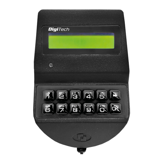
Installation instructions DigiTech Models and characteristics Model Variant T9510/BR – Keypad in metal. Black color /DL with Dallas key reader. with rubber membrane foil keypad in black color. Accessories Code Description T20019/T Cabling interface/Adapter. L4001 Large battery box for 6 size C 1,5V batteries. N620/A 9V Battery box with alarm interface. -
Page 4: Certifications
° C and in an environment with non-condensing humidity between 25% and 90%. The mounting dimensions are standard (magic module). For keypad and lock installation, use only the screws provided by Tecnosicurezza. Any other screw must be approved in advance. - Page 5 Any component to be fixed to the lock bolt must be previously approved by Tecnosicurezza before installation. In any case, the maximum load must not exceed 4 N for T5101/M and 30 N for the reinforced model T5101/MP.
-
Page 6: Keypad Dimensions
Installation instructions DigiTech Keypad dimensions STANDARD mounting VERTICAL mounting SwingBolt lock dimensions T5101 6 of 20 II_ DigiTech_05_eng... -
Page 7: Deadbolt Lock Dimensions
Installation instructions DigiTech T5100 DeadBolt lock dimensions T5101/D T5100/D II_DigiTech_05_eng 7 of 20... -
Page 8: Latchbolt Lock Dimensions
Installation instructions DigiTech LatchBolt lock dimensions T5101/S T5100/S MotorLock dimensions T5101/M & T5101/MP 8 of 20 II_ DigiTech_05_eng... -
Page 9: Motor Latchbolt Lock Dimensions
Installation instructions DigiTech Motor LatchBolt lock dimensions T5101/M/S Fixed keypad installation instructions Insert the keypad cable inside the hole on the safe door and connect it to the lock connector "1/ENT". Lift the keypad membrane and, making sure that the connection cable and the battery cable are not damaged by the keypad case, fix the screws to the relative threaded holes on the safe door. -
Page 10: Swingbolt Lock Installation Instructions
1 mm. The bolt must be able to move freely without force being applied to it. The maximum load applicable to the bolt must not exceed 1KN. Contact Tecnosicurezza in case of heavier loads. -
Page 11: Deadbolt And Latchbolt Locks Installation Instructions
5 mm clearance between the lock bolt and the blocking bar of the boltwork. The maximum load applicable to the bolt must not exceed 1 KN. Contact Tecnosicurezza in case of heavier loads. The LatchBolt lock is specially designed to ensure self locking when the door closes. - Page 12 Installation instructions DigiTech T5100/S The distance between the LatchBolt lock and the locking edge must be between a minimum of 3 mm and a maximum of 8 mm. When locked, there must be a 0.5 mm gap between lock bolt and locking surface.
-
Page 13: Motorlock And Motor Latchbolt Locks Installation Instructions
Installation instructions DigiTech Secure the cable inside the special groove located on the lock cover, ensuring that it is not stretched when turning the spindle. Fix the lock using the appropriate mounting screws. Connect the keypad cable to the lock connector "ENT", making sure it is fully inserted and locked. - Page 14 8 seconds (smart reclosure). The maximum load applicable to the bolt must not exceed the limit values specified in the table below. Contact Tecnosicurezza in case of heavier loads. Lock reference Lock version Maximum force to apply...
-
Page 15: Functional Test
Repeat the functional test several times before closing the safe door. Failure to follow these installation instructions or opening the lock by personnel not authorized by Tecnosicurezza will void the warranty II_DigiTech_05_eng 15 of 20... -
Page 16: Ce Declarations
DigiTech: T951-x Il sottoscritto Franco Miller, in veste di Presidente CdA e Legale Rappresentante della società Tecnosicurezza S.p.A., con sede in San Giovanni Lupatoto (Verona) Via Cesare Battisti 276, dichiara sotto la propria responsabilità, che il suddetto prodotto soddisfa per progettazione e costruzione i requisiti delle direttive di: compatibilità... - Page 17 DigiTech: T51-xx Il sottoscritto Franco Miller, in veste di Presidente CdA e Legale Rappresentante della società Tecnosicurezza S.p.A., con sede in San Giovanni Lupatoto (Verona) Via Cesare Battisti 276, dichiara sotto la propria responsabilità, che il suddetto prodotto soddisfa per progettazione e costruzione i requisiti delle direttive di: compatibilità...
- Page 18 Installation instructions DigiTech NOTES 18 of 20 II_ DigiTech_05_eng...
- Page 19 Installation instructions DigiTech NOTES II_DigiTech_05_eng 19 of 20...
-
Page 20: Correct Disposal Of This Product
Contacts GLOBAL HEADQUARTERS USA HEADQUARTERS SPAIN HEADQUARTERS Tecnosicurezza SpA Tecnosicurezza Inc. Tecnosicurezza Sa Via Cesare Battisti, 276 50, Thomas Lane C/Menor, 4 - Nave 10 37057 San Giovanni Lupatoto Pol.
Need help?
Do you have a question about the DigiTech T9510/BR and is the answer not in the manual?
Questions and answers