Table of Contents
Advertisement
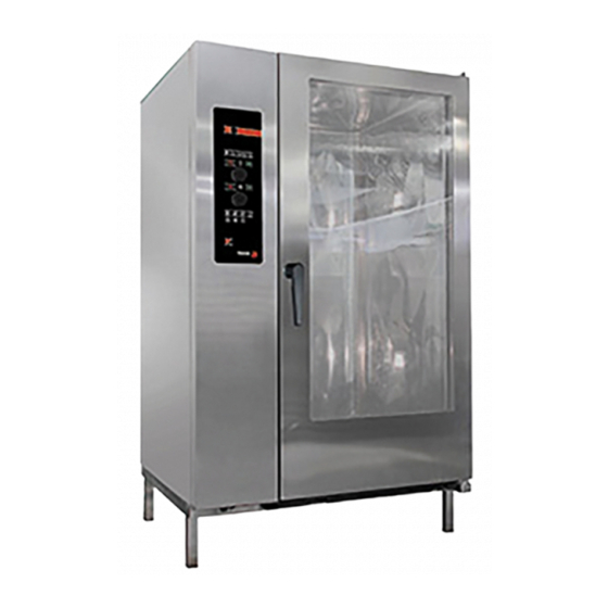
TECHNICAL MANUAL OVENS
TECHNICAL MANUAL OVENS
TECHNICAL MANUAL OVENS
TECHNICAL MANUAL OVENS
TECHNICAL MANUAL OVENS
TECHNICAL MANUAL OVENS
TECHNICAL MANUAL OVENS
TECHNICAL MANUAL OVENS
TECHNICAL MANUAL OVENS
TECHNICAL MANUAL OVENS
TECHNICAL MANUAL OVENS
TECHNICAL MANUAL OVENS
"ADVANCE CONCEPT"
"ADVANCE CONCEPT"
"ADVANCE CONCEPT"
"ADVANCE CONCEPT"
"ADVANCE CONCEPT"
"ADVANCE CONCEPT"
"ADVANCE CONCEPT"
"ADVANCE CONCEPT"
"ADVANCE CONCEPT"
"ADVANCE CONCEPT"
"ADVANCE CONCEPT"
"ADVANCE CONCEPT"
"ADVANCE PLUS"
"ADVANCE PLUS"
"ADVANCE PLUS"
"ADVANCE PLUS"
"ADVANCE PLUS"
"ADVANCE PLUS"
"ADVANCE PLUS"
"ADVANCE PLUS"
"ADVANCE PLUS"
"ADVANCE PLUS"
"ADVANCE PLUS"
"ADVANCE PLUS"
"ADVANCE"
"ADVANCE"
"ADVANCE"
"ADVANCE"
"ADVANCE"
"ADVANCE"
"ADVANCE"
"ADVANCE"
16/11/2012
1
Advertisement
Table of Contents


Need help?
Do you have a question about the ADVANCE CONCEPT and is the answer not in the manual?
Questions and answers
Why not working the display
The display may not be working on the Fagor CONCEPT because the control card, which includes the display interface, may not be present or installed. The context states "NO LLEVA 12 V DISPLAY" and "NO LLEVA" multiple times, indicating that certain models do not include specific components like the display or control cards.
This answer is automatically generated