Table of Contents
Advertisement
Quick Links
Advertisement
Table of Contents

Subscribe to Our Youtube Channel
Related Manuals for CZone 80-911-0009-00


Summary of Contents for CZone 80-911-0009-00
- Page 1 Output Interface (OI) User & Installation Manual V2.0...
- Page 2 EN / CZone® Output Interface (OI) User & Installation Manual Copyright This document is copyright 2018 under the Creative Commons agreement. Rights are granted to research and reproduce elements of this document for non-commercial purposes on the condition that BEP Marine is credited as the source.
-
Page 3: Table Of Contents
EN / CZone® Output Interface (OI) User & Installation Manual TABLE OF CONTENTS GENERAL INFORMATION Use of this manual Guarantee Specifications Quality Validity Of This Manual Liability Changes To The Output Interface SAFETY AND INSTALLATION PRECAUTIONS Warnings And Symbols Use For Intended Purpose... -
Page 4: General Information
EN / CZone® Output Interface (OI) User & Installation Manual 1 GENERAL INFORMATION USE OF THIS MANUAL Copyright © 2016 BEP Marine. All rights reserved. Reproduction, transfer, distribution or storage of part or all of the contents in this document in any form without the prior written permission of BEP Marine is prohibited. This manual serves as a guideline for the safe and effective operation, maintenance and possible correction of minor malfunctions of the Output Interface, called OI further in this manual. ... -
Page 5: Safety And Installation Precautions
EN / CZone® Output Interface (OI) User & Installation Manual 2 SAFETY AND INSTALLATION PRECAUTIONS WARNINGS AND SYMBOLS Safety instructions and warnings are marked in this manual by the following pictograms: CAUTION Special data, restrictions and rules with regard to preventing damage. -
Page 6: Overview
16 mm2 (6AWG) in size, or multiple smaller conductors. No need for specialized crimp terminals and expensive crimp tools to be carried for terminations to CZone, just a blade screwdriver. A protective flexible boot offers protection to the connections from harsh environment conditions. -
Page 7: Oi Hardware Overview
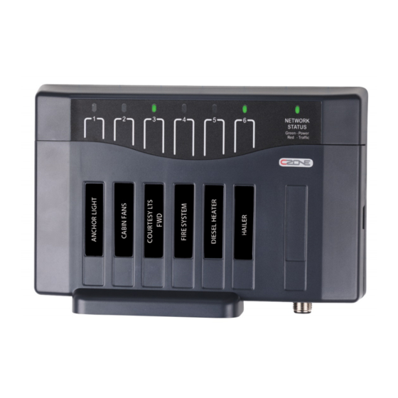
EN / CZone® Output Interface (OI) User & Installation Manual OI HARDWARE OVERVIEW OI With Cover OI No Cover Circuit Status Indicators Output Fuse Label Waterproof Cover DC Positive Stud Circuit ID Labels DC Output Connector Protective Boot 10. Circuit Fuses Network Status Indicator 11. -
Page 8: Led Indicators
EN / CZone® Output Interface (OI) User & Installation Manual LED INDICATORS OI LED Indicators 1. Channel Status LED Indicators Colour Description Extinguished Channel Off Green Solid On Channel On 1 Red Flash Module Not Configured 2 Red Flash Configuration Conflict... -
Page 9: Design
EN / CZone® Output Interface (OI) User & Installation Manual 4 DESIGN • Make a list of all outputs to be wired to the OI and assign each of them to one of the 6 channels. Ensure all cables are appropriately rated for each assigned load. -
Page 10: Mounting
EN / CZone® Output Interface (OI) User & Installation Manual MOUNTING OI Mounting 1. Mount the OI on a vertical surface with the cables exiting downwards. 2. Allow enough space below cable grommet for wiring bend radius. Note - Cable radius determined by wiring manufacturer. -
Page 11: Connections
EN / CZone® Output Interface (OI) User & Installation Manual CONNECTIONS The OI has a convenient output connector that requires no crimping tools and accepts cables from 24AWG to 8AWG (0.5 - 6mm). The unit has no power key and will turn on when power is applied to the network. The module will continue to draw power even when it is not in operation. -
Page 12: Inserting Fuses
EN / CZone® Output Interface (OI) User & Installation Manual INSERTING FUSES The OI provides ignition protected circuit protection for each individual channel via standard ATC fuses (not supplied). Appropriately rated fuses should be selected and installed for each channel to protect the load and the wiring for each circuit. -
Page 13: Network Configuration
EN / CZone® Output Interface (OI) User & Installation Manual NETWORK CONFIGURATION CZone modules communicate with each other over a NMEA2000 CAN BUS network. Each module needs a unique address, this is achieved by carefully setting the dipswitch on each module with a small screwdriver. The dipswitch on each module must match the setting in the CZone configuration. -
Page 14: Module Identification Label
4. Check the software version on the OI with the CZone Configuration Tool and update if necessary. 5. Write the configuration file to the network (Refer to the CZone Configuration Tool Instructions for details on how to write a CZone configuration file). -
Page 15: System Diagram Examples
EN / CZone® Output Interface (OI) User & Installation Manual SYSTEM DIAGRAM EXAMPLES System Diagram... -
Page 16: Ordering Information
EN / CZone® Output Interface (OI) User & Installation Manual 6 ORDERING INFORMATION Part Numbers and Accessories Part Number Description 80-911-0009-00 CZONE OUTPUT INTERFACE C/W CONN & BOOT CZONE OUTPUT INTERFACE NO CONN & BOOT 80-911-0010-00 80-911-0041-00 TERM BLOCK OI 6W PLUG 10 16 PITCH... -
Page 17: Emc Ratings
EN / CZone® Output Interface (OI) User & Installation Manual EMC RATINGS • IEC EN 60945 IEC EN 61000 • FCC Class B • ISO 7637 - 1 (12V Passenger cars and light commercial vehicles with nominal 12 V supply voltage - •... -
Page 18: Declaration Of Conformity
EN / CZone® Output Interface (OI) User & Installation Manual 8 Declaration of Conformity...
Need help?
Do you have a question about the 80-911-0009-00 and is the answer not in the manual?
Questions and answers