Table of Contents
Advertisement
Quick Links
Advertisement
Table of Contents

Related Manuals for CZone COI


Summary of Contents for CZone COI
- Page 1 Combination Output Interface USER’S AND INSTALLATION MANUAL V1.2...
- Page 2 EN / CZone® COI – Combination Output Interface Copyright This document is copyright 2016 under the Creative Commons agreement. Rights are granted to research and reproduce elements of this document for non-commercial purposes on the condition that BEP is credited as the source.
-
Page 3: Table Of Contents
EN / CZone® COI – Combination Output Interface TABLE OF CONTENTS GENERAL INFORMATION Use of this manual Guarantee Specifications Quality Validity Of This Manual Liability Changes To The Combined Output Interface SAFETY AND INSTALLATION PRECAUTIONS Warnings And Symbols Use For Intended Purpose... - Page 4 Figure 3. LED Indicators .......................... 9 Figure 4. Blank Circuit Label ........................10 Figure 5. Blank Input Label ........................10 Figure 6. CZone COI & Masterbus System Example ................12 Figure 7. Detusch HDT-48-00 Crimp Tool ..................... 13 Figure 8. Output Channel Specifications ....................14 Figure 9.
-
Page 5: General Information
CZONE COI NO CONNECTORS 80-911-0120-00 It is obligatory that every person who works on or with the COI is completely familiar with the contents of this manual, and that he/she carefully follows the instructions contained herein. Installation of, and work on the COI, may be carried out only by qualified, authorized and trained personnel, consistent with the locally applicable standards and taking into consideration the safety guidelines and measures (chapter 2 of this manual). -
Page 6: Safety And Installation Precautions
Connection and protection must be done in accordance with local standards Do not work on the COI or system if it is still connected to a power source. Only allow changes in your electrical system to be carried out by qualified electricians ... -
Page 7: Overview
3 OVERVIEW DESCRIPTION The Combination Output Interface (COI) combines multiple input and output devices in to one module, providing a high density 30 channel module which minimizes installation, interconnections and footprint, while delivering best value per circuit. The COI features the same proven, rugged CZone design including IPX5 water ingress protection and complete mechanical fuse protection plus bypass on all circuits as required by ABYC/CE. -
Page 8: Coi Overview
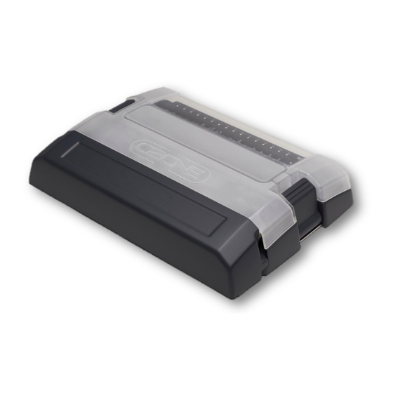
EN / CZone® COI – Combination Output Interface COI OVERVIEW Figure 1. COI with covers POWER Green - Available Red - Low Volts NETWORK STATUS Green - Power Red Flash - Traffic Channel LED Status Codes 10 x RED = Over temperature... -
Page 9: Led Indicators
EN / CZone® COI – Combination Output Interface LED INDICATORS POWER Green - Available Red - Low Volts NETWORK STATUS Green - Power Red Flash - Traffic Figure 3. LED Indicators 1. Circuit Status LED’s Colour Description Extinguished Channel Off... -
Page 10: Labelling
Figure 5. Blank Input Label USB PORT The USB port on the COI allows system software updates and configuration files to be loaded from a USB Memory Stick. This feature is only supported on devices with firmware version 6.11.30.0 or newer. -
Page 11: Writing Configuration To Network
4. Once the system configuration has been updated the following files will be created/updated: a) *.csv - A basic spreadsheet listing information about the system and modules connected to the network. b) CZone USB Result.txt - A text file describing the result of the last operation performed, as well as these instructions. -
Page 12: System Example
EN / CZone® COI – Combination Output Interface SYSTEM EXAMPLE Batt Fuse This drawing is for illustration purposes of the stated product or system. This is not a complete installation drawing and as such should not be relied on as the sole source of information. -
Page 13: Installation
COI Digital Switch Breakout and Cable (optional, refer to page 23 for part numbers) 4 x 8G or 10G (4mm or 5mm) self-tapping screws or bolts for mounting COI to surface HDT-48-00 Deutsch crimp tool for crimping 0.5mm-4mm (20-12AWG) wire ... -
Page 14: Planning
Make a list of all inputs and outputs to be wired to the COI and take note of the output channel ratings and functions as shown in Figure 8. Ensure loads are wired to the appropriate channel for the functionality required. -
Page 15: Deutsch Connector Kit
EN / CZone® COI – Combination Output Interface DEUTSCH CONNECTOR KIT If you have purchased the COI module that includes the Deutsch connector kit (part # 80-911-0119-00), check all components are in the bag before proceeding. Image Part Number Description... -
Page 16: Mounting
1. Remove the COI top cover and locate the 4 mounting screw locators as shown in Figure 11 2. Place the COI on a solid, flat surface. 3. Screw the COI to the surface with 4 x 8G or 10G (4mm or 5mm) self-tapping screws or bolts. CONNECTIONS... - Page 17 4. Insert the connector into the COI and lock into place. 5. Load negatives are not connected to the COI, they must be connected to a common negative bus. Best wiring practice is to locate the negative connections close to the COI so positive & negative wires run together minimizing magnetic fields.
-
Page 18: Figure 13. Coi Digital Switch Breakout Connections
Figure 13. COI Digital Switch Breakout Connections 1. The digital switch input can be used to connect up to 6 CZone digital switches (Push Button or Rocker) to the COI with the optional Digital Switch Breakout. Refer to Page 23 for part numbers. If no digital switches are required, ensure the blanking cap is fitted to maintain the IPX5 rating. -
Page 19: Labels & Fuses
1. Using a marker pen, write the analogue and digital input names matching the input list and physical plug connections. 2. Write the COI module number and location (i.e. COI01 – Engine Room). This should match the module name in the configuration. -
Page 20: Set Dipswitch
8. Check the software version on the COI with the CZone Configuration Tool and update if necessary. 9. Write configuration file to the COI and the rest of the CZone modules on the system (Refer to the CZone Configuration Tool Instructions for details on how to configure the COI). -
Page 21: Specifications
EN / CZone® COI – Combination Output Interface 5 SPECIFICATIONS TECHNICAL SPECIFICATIONS Model Combination Output Interface Article numbers 80-911-0119-00, 80-911-0120-00 Manufacturer BEP Marine New Zealand Output Channels High 4 x 25A Output Channels Low 12 x 10A Dimmable 8 x Analogue Inputs: Positive or Negative Switching, 0-32 Volt, 0-1000 Ohm Resistance Analogue Inputs &... -
Page 22: Figure 16. Coi Dimensions No Covers
EN / CZone® COI – Combination Output Interface DIMENSIONS 339 [13 5/16"] 3 4 5 12 11 10 9 8 339 [13 3/8"] Figure 16. COI Dimensions no covers 339 [13 5/16"] 339 [13 3/8"] Figure 17. COI Dimensions with covers... - Page 23 EN / CZone® COI – Combination Output Interface 6 ORDERING INFORMATION COI Part Numbers and Accessories Part Number Description 80-911-0119-00* CZONE COI C/W CONNECTORS 80-911-0120-00 CZONE COI NO CONNECTORS 80-911-0123-00 CZONE COI CABLE COVER 80-911-0134-00** CZONE COI DIGITAL SWITCH BREAKOUT...
- Page 24 EN / CZone® COI – Combination Output Interface 7 EC DELCARATION OF CONFORMITY Power Products LLC Mailing Address: BEP Marine LTD PO Box 101-739 NSMC Auckland 0632, New Zealand Street Address: 42 Apollo Drive Rosedale, Auckland, 0632, New Zealand Declare under our sole responsibility that the products: ...
Need help?
Do you have a question about the COI and is the answer not in the manual?
Questions and answers