Subscribe to Our Youtube Channel
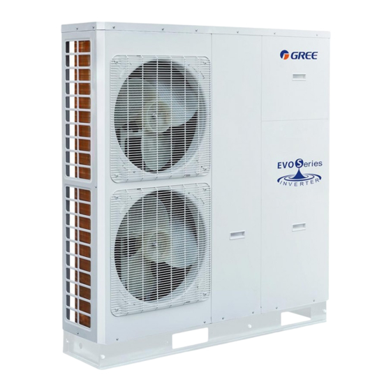
Summary of Contents for Gree Evo Series
- Page 1 Change for life Mini Chiller Unit Installation GREE ELECTRIC APPLIANCES, INC.OF ZHUHAI...
-
Page 2: Table Of Contents
CONTENTS 1.Installation Guides .................. 1 1.1 Installation Positions of the Mini Chiller ..............1 1.2 Matters Need Attention ....................2 2 Filed Supplied Pipes and Valves ............2 3 Service Tools ................... 3 4 Instalaltion Instructions ................. 3 4.1 Installation Examples ....................3 4.2 Pre-Installation ...................... -
Page 3: Installation Guides
Unit Installation 1.Installation Guides WARNING! Installation should be performed by GREE appointed servicemen, or improper installation would lead to ① unusual operation, water leakage, electric shock or fire hazard. The unit should be installed on the foundation which is capable of supporting the unit, or the unit would fall ②... -
Page 4: Matters Need Attention
Unit Installation salty fog and polluted air. 1.2 Matters Need Attention (1) The installation of unit must be in accordance with national and local safety codes. (2) Installation quality will directly affect the normal use of air conditioner unit. The user is prohibited from installation by himself. -
Page 5: Service Tools
Unit Installation 3 Service Tools Name Picture Spanner Screw Driver Pliers Tube Tongs 4 Instalaltion Instructions 4.1 Installation Examples CASE 1: Connection of Terminals for Heating and Cooling (Under floor Loop, Fan Coil Unit, and Radiator) Under Floor Coil Radiator FCU 1 FCU 2 Remote room thermostat (field supplied) - Page 6 Unit Installation Notes: The two-way valve is very important to prevent dew condensation on the floor and radiator while cooling ① mode; Type of thermostat and specification should be complied with installation of this manual; ② The by-pass valve must be installed to secure enough water flow rate, and should be installed at the ③...
- Page 7 Unit Installation Field Installation Diagramof the Electric Heater (with the thermostat) Electric Box 4T26 Main Board AP1 Wiring Board AC Contactor 1 CN26 CN27 Tank-type Electric Heater 4T26 Sensing probe Thermostat AC Contactor 2 Neutral Line (2) See the following statement for installation of two groups of auxiliary electric heaters, including wiring of the AC contactors and the tank-type electric heater.
-
Page 8: Pre-Installation
Unit Installation Wiring of the tank-type electric heater is the same as that stated above. ◆ Field Instalaltion Diagram of the Electric Heater (without the thermostat) Electric Box 4T26 Mainboard AP1 Wiring Board AC Contactor 1 CN26 CN27 4T26 AC Contactor 2 Notes: During installation, the electric heater should be supplied with three-phase power separately. -
Page 9: Outline Dimension Of The Mini Chiller
Unit Installation 4.4 Outline Dimension of the Mini Chiller ◆ HLR8Pd/Na-K, HLR10Pd/Na-K 1390 ◆ HLR12Pd/Na-M, HLR14Pd/Na-M 1390... -
Page 10: Installation Clearance Data
Unit Installation 4.5 Installation Clearance Data 2000 > (1) When moving the monobloc unit, it is necessary to adopt 2 pieces of long enough rope to hand the unit from 4 directions. Included angle between the rope when hanging and moving must be 40°below to prevent center of the unit from moving. -
Page 11: Wiring Of The Terminal Board
Unit Installation ◆ HLR12Pd/Na-M, HLR14Pd/Na-M 4.7 Wiring of the Terminal Board ◆ HLR8Pd/Na-K, HLR10Pd/Na-K... -
Page 12: Wiring Of The 2-Way Valve
Unit Installation ◆ HLR12Pd/Na-M, HLR14Pd/Na-M 4.8 Wiring of the 2-Way Valve The 2-way valve is required to control water flow for cooling operation. The role of 2-way valve is to cut off water flow into the underfloor loop when the fan coil unit is equipped for cooling operation. General Information Type Power... -
Page 13: Wired Controller
Unit Installation WARING! Normal Open type should be connected to wire (ON) and wire (N)for valve closing in cooling mode. ① Normal Closed type should be connected to wire (OFF) and wire (N)for valve closing in cooling mode. ② (ON) : Line signal (for Normal Open type) from PCB to 2-way valve (OFF) : Line signal (for Normal Closed type) from PCB to 2-way valve (N) : Neutral signal from PCB to 2-way valve The 2-way value 2 is reserved without any control program. -
Page 14: Wiring Of The Remote Air Temperature Sensor
Unit Installation 4.12 Wiring of the Remote Air Temperature Sensor Front side Back side Remote Air Temperature Sensor 1.5 Meters Doors Remote Air Environment Temp sensor Electric box Notes: Distance between the monobloc unit and the remote air temperature senor should be less than 15 ①... -
Page 15: Wiring Of The Control
Unit Installation Thermostat Thermostat How to Wire Thermostat (1) Uncover the front cover of the monobloc unit and open the control box. (2) Identify the power specification of the thermostat, if it is 230V , find terminal block XT3 as NO.21~25; Otherwise, if it is 24V, find terminal block XT3 as NO.26~30;... -
Page 16: Commissioning And Trial Run
Unit Installation 5 Commissioning and Trial Run 5.1 Check before startup For safety of users and unit, the unit must be started up for check before debugging. The procedures are as below: The following items shall be performed by qualified repair persons. Confirm together with the sales engineer, dealer, installing contractor and customers for the following items finished or to be finished. -
Page 17: Test Run
Unit Installation 5.2 Test run Test run is testing whether the unit can run normally via preoperation. If the unit cannot run normally, find and solve problems until the test run is satisfactory. All inspections must meet the requirements before performing the test run.


Need help?
Do you have a question about the Evo Series and is the answer not in the manual?
Questions and answers