Table of Contents
Advertisement
Quick Links
Change for life
Service Manual
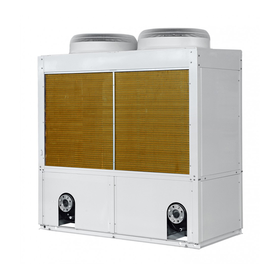
B series modular air-cooled scroll chiller (heat pump)
T1/ R410A /50Hz
Thank you for choosing commercial air conditioners.Please
read this Owner' s Manual carefully before operation and
If you have lost the Owner's Manual, please contact the
local agent or visit www.gree.com or send an email to
Advertisement
Table of Contents
Troubleshooting

Related Manuals for Gree B Series


Summary of Contents for Gree B Series
- Page 1 B series modular air-cooled scroll chiller (heat pump) T1/ R410A /50Hz Thank you for choosing commercial air conditioners.Please read this Owner’ s Manual carefully before operation and If you have lost the Owner's Manual, please contact the local agent or visit www.gree.com or send an email to...
-
Page 2: Table Of Contents
Contents PRODUCT ......................3 1 Introduction ....................3 1.1 Lineup .....................3 1.2 Nomenclature ..................3 1.3 Product features ..................4 1.4 Nominal operating conditions ..............4 1.5 Operation range ..................5 2 Unit performance curves ................5 3 Working principle ...................6 4 Techinical parameters list ................6 4.1 Electrical parameters ................6 4.2 Performance parameters table ..............7 4.3 Scope of supply ..................8 DESIGN AND SELECTION ................10... - Page 3 4 General introduction ..................21 4.1 Homepage ....................22 4.2 Menu page ....................23 4.3 Introduction to the pop-up windows ............24 4.4 Backlight ....................24 5 Operation instructions ..................25 5.1 On/Off ....................25 5.2 Functions ....................26 5.3 Parameter .....................34 5.4 Information ....................36 5.5 E-Clear ....................44 5.6 General ....................45 5.7 Setup of DIP switches on the motherboard ...........48 6 Smart management system .................49...
- Page 4 4.3 Installation environment ................65 4.4 Installation and service space ...............65 4.5 Installation foundation ................66 4.6 Handling and lifting ................66 4.7 Placement of the main unit ..............67 5 Piping and insulation ..................68 5.1 Installation of the water system .............68 5.2 Requirements on piping ................70 5.3 Installation of the expansion tank ............78 5.4 Installation of condensate pipes ............79 6 Electric wiring ....................81...
- Page 5 3 Power distribution ..................109 3.1 Power distribution logic ...............109 3.2 Introduction to the main electric element ..........110 4 Replacement of main parts ................110 4.1 Brief introduction .................110 4.2 Replacement instructions ..............112 5 Routine maintenance .................120 5.1 Repairs to refrigerant leakage .............120 5.2 Air removal ..................121 6 Exploded views and part lists ..............122 7 Maintenance ....................127...
- Page 6 COMPLIANCE identifies a hazard which could lead death or serious injury as well as damage to the property. PREFACE Thank you for selecting Gree’s B series inverter modular air-cooled chiller (heat pump). Please read this service manual carefully before installing and using the product and achieve operating effect. We hereby instruct as below:...
- Page 7 Product Product...
-
Page 8: Product
Product PRODUCT 1 Introduction 1.1 Lineup Cooling Heating capacity capacity Model Power supply Refrigerant Diagram LSQWRF65VM/NaB-X 380-415VAC R410A 3Ph 50Hz/60Hz LSQWRF130VM/NaB-X 1.2 Nomenclature Code description Options Unit LS: chiller Compressor type QW: hermetic scroll/rotor type Default:cooling only Unit function R: heat pump Cooling method of condenser F: air-cooled Rated cooling capacity... -
Page 9: Product Features
Product 1.3 Product features The all-inverter modular air-cooled chillers work outstandingly by virtue of their major features stated below. (1) High efficiency and energy saving The variable-frequency all-round direct current technology enables the unit to make accurate control of itself to operate at a optimum frequency in light of load changes. With shell-and-tube heat exchangers and fins, the unit rated at beyond the national first level. -
Page 10: Operation Range
Product 1.5 Operation range The unit should work within the specified operation range as shown in the table below: Water side Air side Item Leaving water Water temperature Ambient DB temperature (°C) difference (°C) temperature (°C) Cooling 5~20 2.5~6 -15~48 Heating 35~50 2.5~6... -
Page 11: Working Principle
Product 3 Working principle Here are diagrams below to present the constituents and refrigerant flow of the system. Finned heat exchanger 4-way valve Electric expansion valve Compressor Vapor-liquid separator r Shell-and-tube heat exchanger 4 Techinical parameters list 4.1 Electrical parameters Electrical parameters table Compressor Unit... -
Page 12: Performance Parameters Table
Product 4.2 Performance parameters table Model LSQWRF65VM/NaB-X LSQWRF130VM/NaB-X Cooling capacity Heating capacity Rated cooling power 20.9 42.2 Rated heating power 20.1 40.2 Noise dB(A) Power supply 380–415V 3N~50Hz The microcomputer implementing fully automatic control, Operation control displaying the operation state and giving an alarm High-pressure and low-pressure safety cut-out, high- discharge temperature cut-out, antifreeze control, overflow control, phase safety device, water flow safety control,... -
Page 13: Scope Of Supply
Product 4.3 Scope of supply Item Heat pump Modules Three-wire control lines (8m) Accessories for the unit XE73-25/G S (Additionally purchased) Electric control cabinet Auxiliary electric heater Power lines Control lines Connecting hose Thermometer Pressure gauge S= standard O= user prepared P= optional... - Page 14 Design and Selection Design and Selection...
-
Page 15: Design And Selection
Design and Selection DESIGN AND SELECTION Calculate the load for each separate area (cooling load and fresh air load)→Select the terminal unit→Select the main unit→Check the cooling load→Make a confirmation ◆ Load estimate Cooling load per unit of air conditioning area Cooling load Cooling load Building type... - Page 16 Design and Selection Cooling load Cooling load Building type Room type Building type Room type (W/m (W/m Lounge for Business hall 120~160 Stadium judes, coaches 100~140 and athletes Bank Deluxe office Offfce 70~120 120~160 Office building General office Machine room 120~160 90~120 Exhibition hall...
- Page 17 Design and Selection Heating and cooling load (W/m Loading conditions Total Total Building type Exfiltration Fresh Fresh Lighting Density Fresh air cooling heating (W/m (p/m (h-1) capacity capacity Dining room 0.60 Study room 0.50 Reading room 0.20 0.20 0.20 Ward 0.20 0.20 Auditorium...
- Page 18 By the estimated heating load: 12 000×70=840 000W=840kW (3) Select the desired model and quantity. Look up the GREE Technical Guide Manual and it is concluded that 27 SQWRF65VM/NaB-X meet the design requirement. (cooling load: 1 775W, heating load: 1 890kW).
- Page 19 Unit Control Unit Control...
-
Page 20: Unit Control
Unit Control UNIT CONTROL 1 Schematic diagram Description: (1) A water flow cutout is used to judge the water flow rate. When the flow rate is too low, it will trip off, and the control board will send this signal to the display and the water pump. Then, the display will tell there is an error, the water pump will stop and the unit will stop or will not start. - Page 21 Unit Control (6) Defrost temperature sensor is used to detect the liquid tube temperature of fins serving the condenser, which will determine whether to start the fan. When the sensed temperature is too high or this sensor fails, the control board will detect and send this signal to the display. Then, the display will tell there is an error and the unit will stop or will not start.
-
Page 22: Operation Flowchart
Unit Control 2 Operation flowchart 2.1 Cooling... -
Page 23: Heating
Unit Control 2.2 Heating... -
Page 24: Key Control Logics
Unit Control 3 Key control logics 3.1 Cooling control ◆ Freeze-up protection For each single unit, when the anti-freezing temperature or the leaving water temperature is lower than the limit value, freeze protection will work; when the anti-freezing temperature and the leaving water temperature go higher than the normal value, freeze protection will quit. -
Page 25: Automatic Anti-Freezing Operation
Unit Control Shutdown upon errors: the compressor stops firstly and the fan, while the water pump keeps running. 3.3 Automatic anti-freezing operation For each single unit, when the anti-freezing temperature or the leaving water temperature is lower than the limit value, freeze protection will work; when the anti-freezing temperature and the leaving water temperature go higher than the normal value, freeze protection will quit. -
Page 26: General Introduction
Unit Control the unit with communication fault, when all its compressors stop and then the water pump will follow. (4) Protection against phase loss/reversal When there is phase loss or reversal for power supply, power for the main board will be cut off directly. In this case, there is nothing for the main board. -
Page 27: Homepage
Unit Control 4.1 Homepage Homepage Introduction Unit name, error icon and name, BMS alert Year, month, day, hour, and minute Quantity of the on-line units ON/OFF mode Temperature set point under the corresponding control mode Menu icon Run mode setting On/Off key. -
Page 28: Menu Page
Unit Control Notes: When there is no any operation in ten minutes at any page, except the warming pages as shown in the figure below, it will automatically back to the homepage. 4.2 Menu page Menu page Item Interpretation FUNCTION It is used to access to the function setting pages. -
Page 29: Introduction To The Pop-Up Windows
Unit Control (1) The unit status will be displayed at the left upper corner of the control panel. (2) Generally the unit name is displayed at the left upper corner of the control panel. If there is BMS communication, the BMS alert “Remote Control:On” and the unit name will be displayed circularly in five minutes. -
Page 30: Operation Instructions
Unit Control 5 Operation instructions For functions unavailable for this unit, “N/A” will be displayed or they cannot be set during operation. 5.1 On/Off (1) At the homepage and menu page when the unit is “OFF”, by touching “ON/OFF”, the control panel will access to the following page. -
Page 31: Functions
Unit Control (4)Press “OK” and then the control panel will access to the following “OFF” page. Notes: Upon first power-on, the On/Off status will not be memorized. However, once “ON/OFF memory” is set to “ON” at the function setting page the On/Off status will be memorized upon next power-on. When “ON/ OFF memory”... - Page 32 Unit Control Function page 3 (2) At the function setting page, the last page or next page icon allows the control panel accessing to the last or next function page; the homepage icon allows going back to the homepage; and the back icon allows to the super-menu page.
- Page 33 Unit Control Parameter Name Range Interpretaion Remote monitoring 1~255 address Resetting Enter Except the language setting Field commissioning Enter Factory commissioning Enter (1) Mode At the function setting page, when the unit is OFF, by touching “Mode”, the control panel will go to the corresponding setting page.
- Page 34 Unit Control Notes: (a) It is defaulted to be “Off” upon first power-on. (b) It can be memorized upon power failure. (5) Timer ON/OFF At the function setting page, by touching “Timer ON/OFF”, the control panel will go to the corresponding setting page.
- Page 35 Unit Control Then, touch “□” under “Select” to make it turn to “√”, which then indicates the corresponding period has been invalidated. After that, press the saving icon at the upper right corner to save this setting, or press the back icon at the upper left corner to give up this setting.
- Page 36 Unit Control Enable the defrosting function of the selected unit. When “□”turns to √”, it indicates manual defrosting function for this unit has started as shown in the figure below. When disable the defrosting function for this unit, there will be a pop-up window, saying, “Unit XX defrosting has not finished, are you sure to stop it manually?”...
- Page 37 Unit Control (d) Do not activate this function for two or more units. (e) When this function has been enabled for five minutes, however the unit fails to perform defrosting. Then, this function will be disabled, also warning “Manual defrosting stops automatically!” (f) When this function has been enabled, however actual defrosting will be delayed for some time.
- Page 38 Unit Control (11) Remote monitoring address At the function setting page, by touching “Remote monitoring address”, the control panel will go to the address input page, where digits from 1 to 255 will be input through the numeric keypad. After that, by touching “OK”, this setting will be saved and the control panel will go back to the function setting page.
-
Page 39: Parameter
Unit Control (13) Field commissioning At the function setting page, by touching “Field commissioning”, the control panel will go to the password input page. Then, by entering correct passwords, it will access to the “Field commissioning” page, where is used mainly for system parameter setting for repair and maintenance. Notes: Arbitrary change to “field commissioning”... - Page 40 Unit Control (2) At the parameter setting page, by touching the last page and next page icons, the desired setting page can be selected. Parameter setting page 2 (3) By touching the desired parameter, the controller will access to the corresponding setting pages as shown in the figure below.
-
Page 41: Information
Unit Control 5.4 Information (1) At the menu page, by touching “INFO.”, the control panel will go to the following page. (2) At the above page, by selecting the desired unit, the control panel will go to the following page. Notes (a) It is only available for the on-line units, namely those in white. - Page 42 Unit Control Unit with a red point ◆ Status By touching“Status”, the control panel will go to the stats pages, where it is able to check the running status of the unit. Status page 1 Status page 2 Status page 3...
- Page 43 Unit Control Status page 4 Nmae Status Nmae Status Off; Cooling; Heating; System status Defrosting; Automatic Four-way valve 2 On; Off antifreeze Compressor 1 On; Off Electric heater 1 On; Off Compressor 2 On; Off Electric heater 2 On; Off Fan 1 On;...
- Page 44 Unit Control Parameter page 2 Parameter page 3 Parameter page 4 Name Name Entering water-T Suction temperature 1 Leaving water-T Suction temperature 2 Defrosting temperature 1 Shell-and-tube inlet-T 1 Defrosting temperature 2 Shell-and-tube inlet-T 2 Discharge temperature 1 Shell-and-tube outlet-T 1 Discharge temperature 2 Shell-and-tube outlet-T 2 Anti-freezing-T...
- Page 45 Unit Control Notes: (a) “N/A” will be displayed when the temperature value for the corresponinidng mode or unit doesn not exist or is invliad. (b) For item 7 and 8 in the table above, when “Mode” is set to “Cool”, only “Anti-freezing-T” will be displayed;...
- Page 46 Unit Control Short name Full name Sys1 low pressure Protection against low pressure of system 1 Sys2 low pressure Protection against low pressure of system 2 Entering water TSE Entering water temperature sensor error Leaving water TSE Leaving water temperature sensor error Anti-F/anti-H TSE Anti-freeze/anti-over-heating temperature sensor error Ambient TSE...
- Page 47 Unit Control Short name Full name Heat sink or IPM or PFC temperature sensor error of HS-IPM-PFC SEC1 compressor 1 Charging circuit-EC1 Charging circuit error of compressor 1 DC busbar under-voltage or voltage drop error of DC under-voltageC2 compressor 2 DC busbar over-voltage or voltage drop error of compressor DC over-voltageC2 IPM errorC2...
- Page 48 Unit Control Short name Full name HS-IPM-PFC SEF2 Heat sink or IPM or PFC temperature sensor error of fan 2 Charging circuit-EF2 Charging circuit error of fan 2 ◆ Error records By touching “Error record”, the controller will access to the current error record page. Notes: Each error record includes the error number, error name, month, day, hour, and minute.
-
Page 49: E-Clear
Unit Control ◆ Bar codes By touching “Bar code”, it will go to the bar codes page, as shown in the figure below. 5.5 E-Clear At the menu page, touching “E-clear”, it will access to the error clear page. At this page, it is able to operate error clearing and discharge failure unlocking. -
Page 50: General
Unit Control (b) When touching “No” or “Cancel”, this operation will quit and the unit will do not do any operation. (c) After this operation, all recovered errors for all on-line units will be cleared; for those unrecovered, there will still be alerts. (2) Unlock discharge failure At the “ERROR CLEAR“... - Page 51 Unit Control (1) Key tone At the function setting page, by touching “GENERAL”, the control panel will go to the corresponding setting page. Then, by touching “Key tone”, it can be set to “On” or “Off’, as shown in the figure below. General page with activated key tone General page with deactivated key tone (2) Backlight...
- Page 52 Unit Control The setting value for the system clock can be changed by the sliding the blue digits. Then, by touching the saving icon, this setting will be saved and rightly take effective. While, by touching the back icon, this setting will not be saved and the controller will back to the general setting page.
-
Page 53: Setup Of Dip Switches On The Motherboard
Unit Control (5) Program information At the function setting page, by touching “GENERAL”, the control panel will go to the corresponding setting page. Then, by touching “Program information”, the controller will access to the program checking page, as shown in the figure below. Notes: “Version”... -
Page 54: Smart Management System
Unit Control 6 Smart management system 6.1 Long-distance monitoring/BMS interface This long-distance monitoring system allows users through a computer to remotely monitor up to 255 variable-frequency modular-type chillers, including turning on/off the units, setting parameters, giving alarms for malfunctions, which is an efficient tool for management of intelligent air conditioning systems for modern buildings. -
Page 55: Hardware
Unit Control The second part refers to the communication network, that is, the communication lines and the connected hardware. The third part is the patching board responsible for the data exchange between the air conditioning system and the monitoring PC. When there is only one unit, the patching board is not required and RS485 signal lines from BMS can be directly connected to the BMS port of the control panel. -
Page 56: Model Selection Instructions
Unit Control 6.4 Model selection instructions ◆ Rules for model selection Supply scope Item Model Type Remarks CPU: Pentium 4 or above Memory: 512M or above Hard disc: 30G or above Computer Serial port: 1 at least Opertion system: Windows XP/ Windows 2003/Windows Vista/ Windows 7 It is for remote monitoring other... - Page 57 Unit Control ◆ Examples of model selection Example 1 This project consists of 3 LSQWRF65VM/NaB-X, one control panel and BMS. The maximum communication distance is within 800m. The BMS interface is RS232 and one converter is required. Name Code Quantity Air conditioning system EL01500870 1 (3 LSQWRF65VM/NaB-X)
- Page 58 Unit Installation Unit Installation...
-
Page 59: Unit Installation
Unit Installation UNIT INSTALLATION 1 Installation flowchart Technical disclosure Material purchase Installation of condensate pipes Installation of the Connection of the Check for insulation Piping Wiring main unit water system location Installation of Pressure test connection pipes Anti-corrosion and Insulating insulation of pipes Cleaning of pipes Fixing... -
Page 60: Preparations Before Installation
2.1 Precautions for installation WARNING • Installation should be performed by GREE appointed servicemen, or improper installation would lead to unusual opera tion, water leakage, electric shock or fire hazard. • The unit should be installed on the foundation which is capable of supporting the unit, or the unit would fall off or even lead to personal injury. -
Page 61: Importance Of Installation
Unit Installation CAUTION • Always use safety outfits at the construction site. • No smoking and no drunken operation are allowed at the construction site. • Wear no gloves and tighten the cuff when operating the machinery and electrical equipment. Do not maintain it during operation. -
Page 62: Selection Of Installation Materials
Unit Installation Caused influences Typical problems Unqualified vibration reduction measures Unqualified vibration reduction would lead to in creased vibration and measures noise, or even abnormal operation. No protective sleeve for the wall-thru Water leak would be led to by friction water pipes between the wall-thru pipe and the wall. - Page 63 Unit Installation 2) Insulation Typically the refrigerant copper tubes, air ducts, chilled water tubes and condensation tubes should be thermally insulated by the commonly used plastic insulation rather than glass wool, PE or PEF. Thickness listed in the table above all is larger than the required thickness. Special adhesives for insulation should be used, as shown in the figure below.
- Page 64 Unit Installation • Shut-off valve and throttling Valve: its nominal diameter is limited to 200 or below. The shut-off valve is used to cut off the tube flow and the throttling valve is mainly used to throttle the tube flow. •...
- Page 65 Unit Installation • Selection of valves Item Selection principle Butterfly valves for the inlet and outlet of the chilled water and cooling water tubes. Butterfly valves for the water pump inlet; check and butterfly valves for the water pump outlet. By-pass valves between the water header and the distributor.
- Page 66 Unit Installation Item Selection principle It depends on the installation location, upstream water pressure, sealing performance and size of the water hammer etc. Swing, ball and shuttle-type check valves are good choices when pressure upstream is small. Type Spring-type check valves are good choices when there is high requirement Selection of on the sealing performance.
-
Page 67: Tools
Unit Installation 3 Tools 3.1 Cutting and finishing tools It mainly includes: abrasive-disc cutter, hand abrasive wheel, chain blocks, electric drill, threading machine, pressure test device, handsaw, pipe wrench, box wrench, monkey wrench, hammer, and electric welder etc. 3.2 Measuring tools It mainly includes: steel band tape, level bar, angle square, U-shaped pressure gauge etc. - Page 68 Unit Installation Name Picture Usage Hand Electric Drill Drill holes Steel Band Tape Measure length Leval Bar Judge the levelness Booster Pump to pressurize tubes Oxygen Lance to cut steel tubes...
-
Page 69: Installation Instructions
Unit Installation 4 Installation instructions 4.1 Outline dimensions (1) LSQWRF65VM/NaB-X (unit:mm) Water out Water in 1450 (Anchor bolt 6-M12) 1800 (Anchor bolt 6-M12) 1030 2130 Note: Outline dimensions exclude the height of rubber pad (70mm). (2) LSQWRF130VM/NaB-X (unit:mm) 1650 Water inW ater out 2040 (Anchor bolt 6-M12) 1930 (Anchor bolt 6-M12) -
Page 70: Precautions For Installation
Unit Installation 4.2 precautions for installation (1) Pipelines and electric lines should be correctly connected. (2) Rubber pads and rubber flexible connectors should be used during installation for noise and vibration reduction. (3) Under subzero climate, when the heat pump runs for cooling, anti-freeze liquid is required. (4) Dedicated lugs should be used for lifting. -
Page 71: Installation Foundation
Unit Installation Air inlet Inlet Inlet Inlet >2000 >2000 >1000 Air inlet Inlet Inlet Inlet >2000 >1000 >2000 4.5 Installation foundation (1) The installation foundation should be designed by qualified designers. (2) The foundation should be made of cement or steel structure and be capable of supporting the weight of the unit. -
Page 72: Placement Of The Main Unit
Unit Installation The unit should be moved by the forklift or hoisting machine. During lifting, the canvas lifting or steel ropes in use should be of enough strength and go through the based and then bundled tightly. The unit should be lifted stably from four corners. Meanwhile, be sure there should be protective pads to prevent lifting ropes contacting with the unit. -
Page 73: Piping And Insulation
Unit Installation 5 Piping and insulation 5.1 Installation of the water system Considerations stated below shall be taken carfelly for the water system. (1) Each water inlet and outlet should be labeled properly to avoid misconnection. (2) A flexible connector should be used at the chilled water outlet to reduce vibration transmission. (3) A manometer, a thermometer and a gate valve shall be installed at the chilled water inlet /outlet. - Page 74 Expansion tank AB CN Water pump (backup) AB CN Water pump Auxiliary electric heater Legends To connect the drain pipe AB CN Monometer Check valve Manual exhaust valve Temperature limiter To connect the distribution box Water pump Flexible connector Thermometer Filter Stop valve Automatic exhaust valve...
-
Page 75: Requirements On Piping
Unit Installation Follow the steps of water system drainage. (1) Loosen screws around the panel and then take down it. Step one: remove panels (2) Remove anticlockwise the blind plug located at the bottom of the heat exchanger to let the chilled water flow out. - Page 76 Unit Installation See the table below for the installation standards of the pipes. Item Allowable deviation Inspection method DN≤100mm 2L‰, max.440mm Straightness By the ruler, tape measurement DN>100mm 3L‰, max.460mm Verticality 25L‰, max.425mm By the ruler, tape measurement Interval of Parallel Pipes 15mm By the ruler, tape measurement Parallelism of Parallel Pipes...
- Page 77 Unit Installation (3) Prefabricate pipes 1) Make out the installation drawing which clearly indicates the branch pipes, pipe diameter, reduced pipes, location of valves, installation dimensions etc. Then, prefabricate pipes in accordance this installation drawing. Pipes should be processed with dedicated cutting machine, leaving no burrs at the pipe ends.
- Page 78 Unit Installation (5) Install pipes Supply and return water pipes with the diameter of being or being less than DN 32 should be thread connected, and pipes with the diameter of being or larger than DN40 should be welded. Those which must be detachable should be flange connected.
- Page 79 Unit Installation • Welding should be done by the qualified welder. In welding, there should be a wind, rain, or snow guard. The environmental temperature for welding can’t be lower than -20°C. A 250mm groove for welding should be preheated to 100°C. •...
- Page 80 Unit Installation 5) Installation of valves and water filters • Installation location, height and direction of valves should be correct. And they should be arranged orderly within a deviation of 3mm in the same plane. • The valve stem can’t be downward but toward the direction which will facilitate its operation. •...
- Page 81 Unit Installation 4) Raise the pressure to the test pressure and the test pressure should be kept for 10 minutes. Then, lower the pressure to the working pressure and the working pressure should be kept for 60 minutes. No leakage through the visual inspection indicates it is satisfactory. 5) The filling water test is taken for the condensate water system.
- Page 82 Unit Installation Notes: For the riser pipes, when the floor height is or less than 5m, there should be a bracket tray for each floor; when the floor height is larger than 5m, there should be at least two bracket trays 200mm ahead of the riser pipes.
-
Page 83: Installation Of The Expansion Tank
Unit Installation (9) Take protection measures to finished products 1) Prefabricating, anti-corrosion treatment, setup, and pressure test procedures go closely one by once. If interrupted, the open mouth of pipes should be closed to prevent foreign matter entering. 2) Installed pipes can’t be taken as the lifting center, and also can’t be stepped on. 3) Pipe repair should be finished prior to external decoration and do not damage any wall and floor finished product after external decoration. -
Page 84: Installation Of Condensate Pipes
Unit Installation (7) For the two-pipe air conditioning system, when there is only one expansion water tank for cold and hot water, its effective volume should be figured out based on the heating conditions. (8) When the water tank is or higher than 1500mm, it should have ladders both inside and outside of the water tank. - Page 85 Unit Installation When the three-way valve is used for the condensate pipe, its straight two connectors should be kept at the same level as shown in the figure below. Tee joint When there are several indoor units at the same floor, their condensate is usually drained out through one main pipe.
-
Page 86: Electric Wiring
Unit Installation Insulation should be thickened at humid areas. You could follow the procedures of insulating refrigerant pipes. (3) Fastening The insulating tube is just required to be bundled and fastened at the supporting bracket. 6 Electric wiring 6.1 Safety precautions NOTE •... - Page 87 Unit Installation ■ LSQWRF130VM/NaB-X Control output neutral line Control output contactor (electric heater 2; 220V) Control output neutral line Control output contactor (electric heater 1; 220V) Romote start/stop Romote start/stop Control output neutral line Control output contactor (user water pump 2; 220V) Control output neutral line Control output contactor (user water pump 1;...
-
Page 88: Specification Of Power Supply
Unit Installation 6.3 Specification of power supply See the table below for selection of the power lines and the air switches. Min. sectional area of the power cable (mm Capability of the Model Power supply air switch (A) Live Neutral Earth line line... -
Page 89: Wiring Of The Electric Control Cabinet
Unit Installation 6.4 Wiring of the electric control cabinet (1) LSQWRF65VM/NaB-X... - Page 90 Unit Installation (2) LSQWRF130VM/NaB-X...
-
Page 91: Filed Wiring
Unit Installation 6.5 Filed wiring Below are safety codes that should be followed. (1) All wiring shall comply with applicable codes and engineering requirements. (2) All field wiring shall be performed by qualified electricians. (3) Never perform wiring before the power supply is cut off. (4) Any damage caused by the improper external wiring shall be at the installer’s expense. -
Page 92: Networking And Wiring Between Units
Display panel 130 Electric box 130 Electric box 65 Electric box 65 Electric box Main Main Main Main Main Main board PC board PC board PC board PC board PC board PC to connect from the next unit to the last unit LeftR ight LeftR... - Page 93 • Install the remote monitoring software at the PC. • Based on GREE provided Modbus protocol, the user can do second development to this protocol. • Note: those enclosed by the dotted lines indicate the remote monitoring equipment. When the quantity of the display panel exceeds 30 or length of the communication line exceeds 800m, extra photoelectric relay is required.
-
Page 94: Electric Wiring Digram
Unit Installation 6.7 Electric wiring digram (1) LSQWRF65VM/NaB-X... - Page 95 Unit Installation (2) LSQWRF130VM/NaB-X The electric wiring diagram stuck to the main body of the unit always prevail.
-
Page 96: Jumpers
Unit Installation 6.8 Jumpers When it is required to replace the main board, be sure the main board can match with the applicable jumpers. Jumpers list Model Code Jumper no. Matched compressor LSQWRF65VM/NaB-X 4202021903 QXFS-H80zN345K LSQWRF130VM/NaB-X 4202021908 QXFS-H80zN345K... - Page 97 Test Operation, Troubleshooting and Maintenance Test Operation, Troubleshooting and Maintenance...
-
Page 98: Test Operation, Troubleshooting And Maintenance
Test Operation, Troubleshooting and Maintenance TEST OPERATION, TROUBLESHOOTING AND MAINTENANCE 1 Commissioning 1.1 Flowchart of commissioning 1.2 Safety precautions for commissioning WARNING • Safety measures should be taken during indoor operation. Any commissioning and service men should grasp and observe safety regulations of construction work. •... -
Page 99: Check Before Commissioning
Test Operation, Troubleshooting and Maintenance ◆ Tools Name Image Name Image Pressure gauge Digital volt-ohmmeter Spanner Clip-style ammeter Phillips screwdriver Leak detector Straight screw driver Megohmmeter 1.4 Check before commissioning ◆ Completeness check to the main unit (1) Is the surface of the unit in good condition? (2) Is there leak at any pipe connector? (3) Is any part damaged? ◆... -
Page 100: Check For Initial Run
Test Operation, Troubleshooting and Maintenance (7) Run the chilled water pump and see: is the water pressure stable? do the reading values of water pressure change slightly? Is the running ampere in the rated range? If not, figure out and eliminate the causes. - Page 101 Test Operation, Troubleshooting and Maintenance ◆ Check for a single unit (1) Commission one single unit first and stop all others. (2) Do its compressor, fans and the 4-way valve run normally without any unusual noise? (3) Is the voltage phase difference lower than ±2%? (4) Voltage phase difference =(phase difference between the max and average voltage)/(average voltage)×100%.
-
Page 102: Troubleshooting
Test Operation, Troubleshooting and Maintenance 2 Troubleshooting 2.1 View on errors (1) At the menu page, by touching “INFO.”, the control panel will go to the following page. (2) At the above page, by selecting the desired unit, the control panel will go to the following page. Notes (a) It is only available for the on-line units, namely those in white. - Page 103 Test Operation, Troubleshooting and Maintenance Unit with a red point By touching “Error”, the control will access to the error check page. When there is no any error, the control panel will show as below. Notes: The controller can display real-time errors and all real-time errors can be displayed there. When the quantity of error exceeds 5, by touching the last or next page icon, the desired error can be checked.
-
Page 104: Error List
Test Operation, Troubleshooting and Maintenance 2.2 Error list Error name Error source Protection logic When the pressure is too high or the current exceeds the set point, the corresponding compressor will stop and the indicating LED on the control High-pressure protection High-pressure protection panel will light on and the error in formation will be displayed on the... -
Page 105: Errors Identifying Of Systems
Test Operation, Troubleshooting and Maintenance Error name Error source Protection logic When phase loss/reversal occurs, Phase loss/reversal protection Phase protector the phase protector will cut off the power supply to the main board. When a single unit detects its flow switch is open, this module will Protection for the water flow Contact... - Page 106 Test Operation, Troubleshooting and Maintenance 3) Inner collision of fans Blades of a fan are probably seen deformation, mounted out of norms, running in imbalance, contacting each other. Fans could contact the housing or bottom framework. Axials may run unstably. There may be unwanted substance. (3) Testing To locate specific problems, you need to use instruments and meters to test the permance or status of units.
-
Page 107: Flow Chart Of Troubleshooting
Test Operation, Troubleshooting and Maintenance 2.4 Flow chart of troubleshooting (1) High pressure protection High pressure protection Do the cooling and Correct modes heating modes reverse? Does the fan stop running or run reversely? Or do water Check the fan pumps turn off or indicate flow deficiency? Does the electric... - Page 108 Test Operation, Troubleshooting and Maintenance (2) Low pressure protection Low pressure protection Do the cooling and Correct modes heating modes reverse? Does the fan stop running or run reversely? Or do water pumps Check the water pump. turn off or indicate flow deficiency? Does the electrostatic Replace the coils of the...
- Page 109 Test Operation, Troubleshooting and Maintenance (3) High-temperature discharge protection High discharge temp protection Does the discharge Is the resistance of the Replace the discharge temperature go to temperature sensor temperature sensor. 125°C? normal? Replace the damaged main board. Does the electrostatic Replace the coils of the expansion valve work electrostatic expansion valve...
- Page 110 Test Operation, Troubleshooting and Maintenance (4) Phase protection Phase loss/reversal protection Is the phase sequence Adjust the wiring incorrect? Is there phase loss? Check the power supply. Is the phase protector Replace the phase damaged? protector. If this occurs frequently, the Does the controller main board should be alarm incorrectly?
- Page 111 Test Operation, Troubleshooting and Maintenance (5) Water flow switch protection Water flow switch protection Does the water pump Start the water pump. not start? Is the the flow switch not Install the flow switch or installed or installed check the installation. improperly? Is the flow switch faulty? Maintain the flow switch.
-
Page 112: Error Identifying Of Controller
Test Operation, Troubleshooting and Maintenance (6) Temperature sensor error Temperature sensor error Is the sensor plug Check the direction of the placed properly into the sensor probe. main board? Remove the sensor and Replace the temperature see if its voltage is sensor. - Page 113 Test Operation, Troubleshooting and Maintenance 2) With motherboards powered up, you could find out any faults according to error codes displayed via nixietubes. 3) Nixietubes may not work well. For instance, a two-digit tube only displays one digit; displayed error codes cannot be found in this Manual. Then, central processing unit (CPU, herein an integrated circuit on a chip that is fixed to its small board) could be proved faulty, and would be replaced .
-
Page 114: Power Distribution
Test Operation, Troubleshooting and Maintenance 6) If wire connection is normal, the drive board is proved faulty and will be replaced. Problem 3: Communication malfunction of a fan circuit board is captured after controller is energized. Possible causes: Improper wiring, power supply fault, DIP fault, broken drive board Checks: 1) Inspect communication lines between a fan circuit board and drive boards for tightness and skipping connectors. -
Page 115: Introduction To The Main Electric Element
Test Operation, Troubleshooting and Maintenance 3.2 Introduction to the main electric element It is used to check if the phase sequence of the power supply is Phase loss/reversal protector correct or if there is power pahse loss. It is used for the running and Intermediate relay fault indicators. - Page 116 Test Operation, Troubleshooting and Maintenance Image Name Function It is intended conduct heat exchange be tween the Shell-and-tube heat exchanger refrigerant and the second refrigerant. At the cooling mode, it is intended to turn the high-temperature high-pressure refrigerant vapor into refrigerant liquid by releasing heat to Finned heat exchanger the cooling medium.
-
Page 117: Replacement Instructions
Test Operation, Troubleshooting and Maintenance 4.2 Replacement instructions Replacement of the compressor Note: be sure there is no refrigerant inside the system and power supply has been cut off before replacement. Steps Image Instructions • Remove screws at the front panel. - Page 118 Test Operation, Troubleshooting and Maintenance Replacement of the compressor Note: be sure there is no refrigerant inside the system and power supply has been cut off before replacement. Steps Image Instructions • Loosen screws at feet of the compressor with a adjustable 4.
- Page 119 Test Operation, Troubleshooting and Maintenance Replacement of the compressor Note: be sure there is no refrigerant inside the system and power supply has been cut off before replacement. Steps Image Instructions 7. Put back the front Put back front panels and panels.
- Page 120 Test Operation, Troubleshooting and Maintenance Replacement of the 4–way valve Note: be sure power supply has been cut off and refrigerant has been reclaimed before replacement. Steps Image Instructions • Do use the one with the same model for replacement. The one with different model can be used after being approved by relative technicians.
- Page 121 Test Operation, Troubleshooting and Maintenance Replacement of the electric expansion valve Note: check the whole system, pipelines and electric lines, cut off power supply and reclaim refrigerant before replacement. Steps Image Instructions • Take out coils. • Loosen screws and take out pipe clamps and rubber pads.
- Page 122 Test Operation, Troubleshooting and Maintenance Replacement of the electric expansion valve Note: check the whole system, pipelines and electric lines, cut off power supply and reclaim refrigerant before replacement. Steps Image Instructions • Solder pipes. • Do charge nitrogen during soldering.
- Page 123 Test Operation, Troubleshooting and Maintenance Replacement of vapor-liquid separator Note: properly reclaim refrigerant, prepare tools and keep good ventilation. Steps Image Instructions 2. De-solder De-solder connection pipes with a connection pipes. soldering gun. Loosen fixed screws and take out 3. Take out the vapor- liquid separator.
- Page 124 Test Operation, Troubleshooting and Maintenance Replacement of vapor-liquid separator Note: properly reclaim refrigerant, prepare tools and keep good ventilation. Steps Image Instructions Inlet 6.When lubricating oil is needed, you need Charge lubrication oil from the inlet to charge it from the of the vapor-liquid separator and inlet of the vapor- then do soldering.
-
Page 125: Routine Maintenance
Test Operation, Troubleshooting and Maintenance 5 Routine maintenance 5.1 Repairs to refrigerant leakage When soapsuds often used to detect leakage of a refrigeration system is applied to possible leakage points. If there are bubbles, leaks occur and need repairs by brazing. If soapsuds does not work, an electronic leak detector is an alternative. -
Page 126: Air Removal
Test Operation, Troubleshooting and Maintenance (2) Refrigerant recharging Charging process Excessive or deficient refrigerant may cause abnormal operation, malfunction or damage to a compressor, so charge volume must comply with the requirements on the unit nameplate which have been decided in strict tests; The figure may serve as a reference; a charge process is as follows (one system as an example): Step 1: Place a refrigerant container on an electronic scale and connect the container and the pressure gauges by a flexible tube. -
Page 127: Exploded Views And Part Lists
Test Operation, Troubleshooting and Maintenance 6 Exploded views and part lists ■LSQWRF65VM/NaB-X... - Page 128 Test Operation, Troubleshooting and Maintenance ■LSQWRF65VM/NaB-X (EL01500870) Part list Name Code Streamlined Dome 26901100008 Axial Flow Fan 1043110000101 Brushless DC Motor 1570412410 Water Tray Sub-Assy 017055060611P Front Panel 012073061207P Rear Panel 012215060048P One Way Valve 07338000112 Steam current Switch 4502800000904 Rear Panel 01221506004801P Dry Evaporator...
- Page 129 Test Operation, Troubleshooting and Maintenance Name Code Electronic Expansion Valve 43044100173 Electronic Expansion Valve 43044100190 Front Panel 012073061212P Terminal board 422000000025 Terminal board 422000000024 Terminal board 422000060011 Phase Reverse Protector 430055060005 Main board 300027060166 Terminal board 420102471 Main board 300027061313 Filter board 30228000015 Drive board...
- Page 130 Test Operation, Troubleshooting and Maintenance ■LSQWRF130VM/NaB-X ■LSQWRF130VM/NaB-X(EL01500860) Part list Name Code Rear Grill 01571100004 Streamlined Dome 26901100008 Axial Flow Fan 1043110000101 Brushless DC Motor 1570412410 Condenser Assy 1100206108001 One Way Valve 07338000112 Temp Sensor Sleeving 05212423 Condenser Assy 1100206108101 Rear Panel 012215060062P Front Panel 012073061526P...
- Page 131 Test Operation, Troubleshooting and Maintenance Name Code Steam current Switch 4502800000901 Temp Sensor Sleeving 05210001 Pressure Protect Switch 4602001583 Pressure Protect Switch 46020015117 Pressure Protect Switch 4602001590 Pressure Sensor 322101035 Pressure Protect Switch 4602001591 Pressure Protect Switch 4602001561 Pressure Protect Switch 46020015131 Filter 07219056...
-
Page 132: Maintenance
Test Operation, Troubleshooting and Maintenance Name Code Electric Box 012017060797 Main Board 300027061313 Radiator 49010252 Main Board 300027060166 Electric Cabinet Assy 100003061106 Reactor 4313017402 Drive Board 300078060140 Electric Expand Valve Fitting 4304413228 Electric Expand Valve Fitting 4304413248 Electric Expand Valve Fitting 4304413219 Electric Expand Valve Fitting 4304413214... - Page 133 Test Operation, Troubleshooting and Maintenance Water quality requirement Cold/hot water Trend Items Circulating Makeup Scalelike Corrosion water water sediment ○ ○ pH(25°C) 6.8-8.0 6.8-8.0 Electrical μs/cm ○ ○ conductivity <400 <300 (25°C) ○ Basic mg(Cl-)/L <50 <50 items ○ mg (SO <50 <50 Acid consumption...
-
Page 134: Freeze Protection In Winter
Test Operation, Troubleshooting and Maintenance • Stop the unit to drain up waste solution. If impossible, drain it with making up water at the same time until all waster solution has been drained out completely (at this time water is transparent and pH is 7). - Page 135 GREE ELECTRIC APPLIANCES, INC. OF ZHUHAI Add: West Jinji Rd, Qianshan, Zhuhai,Guangdong, China, 519070 Tel: (+86-756) 8522218 Fax: (+86-756) 8669426 E-mail: global@cn.gree.com www.gree.com JF0000000...
Need help?
Do you have a question about the B Series and is the answer not in the manual?
Questions and answers