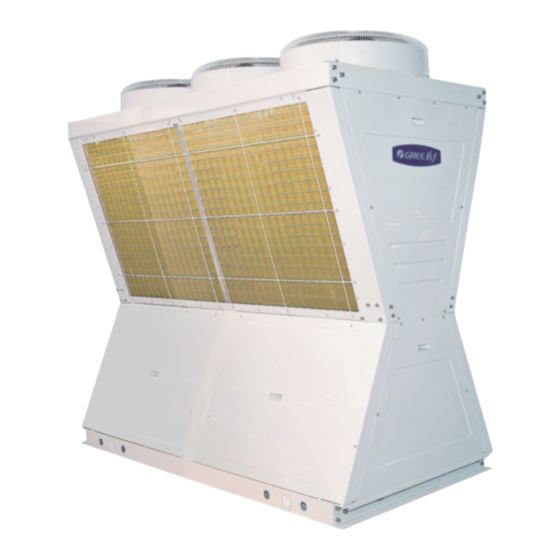
Summary of Contents for Gree C Series
- Page 1 T E C H N I C A L S A L E S G U I D E Capacity Range:60~1216KW T1/R410A/50Hz/60Hz C SERIES...
-
Page 2: Table Of Contents
Nominal Capacity Power Supply Model Refrigerant Ph, V, Hz Model Name LSQWRF65MG/NaC-M 3,380,50 LSQWF65MG/NaC-M LSQWRF80MG/NaC-M 3,380,50 LSQWF80MG/NaC-M LSQWRF130MG/NaC-M 3,380,50 LSQWF130MG/NaC-M LSQWRF160MG/NaC-M 3,380,50 LSQWF160MG/NaC-M R410A LSQWRF65MG/NaC-F 3,220,60 LSQWF65MG/NaC-F LSQWRF80MG/NaC-F 3,220,60 LSQWF80MG/NaC-F LSQWRF130MG/NaC-F 3,220,60 LSQWF130MG/NaC-F LSQWRF160MG/NaC-F 3,220,60 LSQWF160MG/NaC-F GREE Central Air Conditioners... -
Page 3: Nomenclature
GREE Central Air Conditioners... - Page 4 Superior Controls GREE has provided the latest technology in controlling the chillers. The new controller provides a“user friendly”environment for the operator. The control logic is designed to provide maximum efficiency, to help provide continuing operation in unusual operating conditions through proactive controls, and to provide a history of conditions to aid in problem resolutions.
-
Page 5: Features
Under voltage and phase protection: Protects against low incoming voltage as well as single phase, phase reversal. Liquid line solenoid valve: IT coses when the compressor is off to prevent any liquid refrigerant from accumulating in the evaporator. GREE Central Air Conditioners... -
Page 6: Product Data
76 / 22 LSQWF80MG/NaC-F LSQWRF130MG/NaC-F 120 /34 LSQWF130MG/NaC-F LSQWRF160MG/NaC-F 152 / 43 LSQWF160MG/NaC-F EER=Energy Efficiency Ratio at full load-the cooling capacity in Btu's per hour(Btu/h) divided by the power input in watts, expressed in Btu/h per watts((Btu/h)/watt). GREE Central Air Conditioners... -
Page 7: R410A
Depth 2345 2345 2345 2345 2345 2345 2345 2345 nsion Height 2214 2214 2214 2214 2214 2214 2214 2214 Net weight 1000 1780 1980 1050 1880 2080 Gross weight 1010 1800 2000 1060 1900 2100 GREE Central Air Conditioners... - Page 8 2214 2214 2214 2214 2214 Net weight 1000 1780 1980 1050 1880 2080 Gross weight 1010 1800 2000 1060 1900 2100 The operation weight of the unit is equal to 110% of its net neight . GREE Central Air Conditioners...
-
Page 9: Performance Correction
0.84 0.94 1.05 1.17 Water side Air side Difference of the Ambient temp. Db Outlet water temp. in/outlet water temp. Item (℃) (℃) (℃) 5 15 2.5 8 5 46 Cooling 40 50 2.5 8 Heating GREE Central Air Conditioners... -
Page 10: Antifreeze
0.993 0.987 0.980 0.973 Water flow Correction Factor 1.182 1.036 1.060 1.092 1.132 Pressure Drop Correction Factor 1.07 1.10 1.18 1.24 1.30 NOTE: Ethylene and propylene glycol ratio is the scope of Standard 550/590-98 certification program. GREE Central Air Conditioners... -
Page 11: Installation
LSQWRF65MG/NaC-F, LSQWF65MG/ NaC-F Rubber cushion aren t show in this view. b、Graph for the shape and dimensions for LSQWRF130MG/NaC-M, LSQWF130MG/NaC-M , L SQWRF160MG/NaC-M,LSQWF160MG/NaC-M, LSQWRF130MG/Na-F , L SQWF130MG/NaC-F , LSQWRF160MG/NaC-F,LSQWF160MG/NaC-F. Rubber cushion aren t show in this view. GREE Central Air Conditioners... -
Page 12: Mounting Location
Move the unit with roller rod: Put three roller rods with the same size at the bottom of the unit. Each of the rods shall be 1/5 longer than the width of the unit. Keep balance. b. Lifting (reference to the following Graph). 7.3 Mounting Location GREE Central Air Conditioners... - Page 13 2200 2128 1650 LSQWF160MG/NaC-F 7.4 Installation Interspace Room for unit assembly shall be open with free ventilation and without short circuit of air flow. Specific assembly sizes are shown in the graph with unit of mm. GREE Central Air Conditioners...
-
Page 14: Electrical Data
Power cable specifications and air switch types in the following list are recommended for selection. Min. sectional Min. sectional area Air switch capacity of grounding cable area ofpower cable Unit Model ( mm² ) ( mm² ) LSQW(R)F65MG/NaC-M LSQW(R)F65MG/NaC-F LSQW(R)F80MG/NaC-M LSQW(R)F80MG/NaC-F LSQW(R)F130MG/NaC-M LSQW(R)F130MG/NaC-F LSQW(R)F160MG/NaC-M LSQW(R)F160MG/NaC-F GREE Central Air Conditioners... -
Page 15: Field Wiring Diagram
Output Control Electric Heater 1 Contactor (220V live wire) Output Control Zero Line marks: Auxiliary electric heater 1 and 2 and AC contactor output control line of user’s pump can be connected to 11,12,13,14,15and 16 of the terminal (XT3)of any module. GREE Central Air Conditioners... -
Page 16: Microprocessor Controller
Display Data: Return and leaving liquid temperatures, outdoor air temperature, discharge temperature, suction temperature, compressor run status, fan run status, day, date and time, compressor starts/operating hours. GREE Central Air Conditioners... - Page 17 Unit Safeties: Shall be automatic reset and cause compressors to shut down if low leaving chilled liquid temperature, and flow switch operation. Contractor shall provide flow switch and wiring per chiller manufacturer requirements. Alarm Contacts: low leaving chilled liquid temperature, high discharge temperature, high pressure, low pressure. GREE Central Air Conditioners...
-
Page 18: Wired Controller
WIRED CONTROLLER 11.1 Operation View XXXX-XX-XX XX:XX Power C Series Chiller Cool【Heat/Defrost】 On【Off】 【Manual/Timer】 XModules【 【 Error On/off Reset Exit Confirm Power indicator(red): the indicator is on when the wired controller is powered on, or otherwise it is off. 2.... - Page 19 H Water Pump Ass.Heat 1 Module 16 Ass.Heat 2 User Para.Setup 4-Valve 1 4-Valve 2 EXV.1 SystemPara.Setup EXV.2 Exthalpy Inc .EXV.1 Exthalpy Inc .EXV.2 Dis. T Sensor 1 Dis. T Sensor 2 Water_Out EXV . Water_In EXV . GREE Central Air Conditioners...
-
Page 20: Accessories
(necessary) Four-core control connection cord (3 meters) Three-core signal cable (3 meters) Water flow switch Electric control box ---- Auxiliary electric heater Power connection wire Control connection cord Flexible joint Thermometer Pressure gauge Water tank GREE Central Air Conditioners... -
Page 21: Application Data
(30℃) ℉ ( If continuous ope-ration is required for inlet water temperature above 86 (30℃ ), please refer to GREE factory). ℉ Minimum leaving chilled fluid temperature for standard unit is 38 (3.3℃ ) (For lower leaving temperature contact GREE factory). - Page 22 ( for any high flow rate value larger than values in performance tables, please refer to GREE factory). Minimum Cooler Flow: Minimum cooler flow will be based on the maximum permissible AT ℉...


Need help?
Do you have a question about the C Series and is the answer not in the manual?
Questions and answers