Table of Contents
Advertisement
Quick Links
Advertisement
Table of Contents

Related Manuals for Gree HLR8WZNa-M


Summary of Contents for Gree HLR8WZNa-M
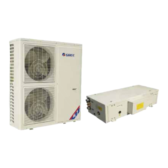
- Page 1 CENTRAL AIR CONDITIONERS MINI CHILLER SERVICE MANUAL T1/R410A/50Hz (GC201104)
-
Page 2: Table Of Contents
CONTENTS PRODUCT ........................2 1 MODELS LIST ..........................2 1.1 Split Type................................2 1.2 Integral Type..............................3 2 NOMENCLATURE........................3 1.1 Split Type................................3 1.2 Integral Type..............................4 3 FUNCTION..........................4 4 PRODUCT DATA........................5 4.1 Product Data at Rated Condition........................5 4.2 Operation Range...............................7 4.3 Electrical Data..............................7 5 PIPING DIAGRAM........................7 UNITS CONTROL.......................9 1 OPERATION FLOWCHART....................9 1.1 Cooling Operation............................9... - Page 3 2.2 Matters of Attention............................23 2.3 Antifreeze.................................23 3 ELECTRIC WIRING WORK....................23 3.1 Wiring Principle.............................23 3.2 SPECIFICATION OF POWER CORD & AIR SWITCH.................23 3.3 WIRING DIAGRAM.............................23 UNITS MAINTENANCE ..................28 1 ERROR CODE LIST........................28 2 FLOW CHART OF TROUBLESHOOTING................29 3 DISASSEMBLY AND ASSEMBLY PROCEDURE OF MAIN PARTS......31 3.1 Split Type................................31 3.2 Integral Type..............................39 4 EXPLODED VIEWS AND PART LIST..................43...
- Page 4 Mini Chiller Service Manual PRODUCT...
-
Page 5: Product
1 MODELS LIST 1.1 Split Type Nominal Power Model Appearance Capacity Supply Product Code Refrigerant Model Name (V,Ph,Hz) Outdoor Unit Indoor Unit HLR8WZNa-M I EM113N0030 HLR8WZNa-M EM113W0030 HLR8WZNa-M O EM113W0031 HLR10WZNa-M I EM113N0020 HLR10WZNa-M 10.0 EM113W0020 HLR10WZNa-M O EM113W0021 HLR12.5WZNa-M I... -
Page 6: Integral Type
Mini Chiller Service Manual 1.2 Integral Type Nominal Power Model Capacity Supply Product Code Appearance Refrigerant Model Name (V,Ph,Hz) HLR22SNa-M EM15000030 HLR25SNa-M EM116N0270 R410A EM116N0260 HLR35SNa-M EM116N0261 EM15000040 HLR45SNa-M EM15000041 Note:1Ton =12000Btu/h = 3.517kW 2 NOMENCLATURE 1.1 Split Type Description Options Mini chiller Product type... -
Page 7: Integral Type
Mini Chiller Service Manual 1.2 Integral Type Description Options Mini chiller Product type R=Heat pump 22=22kW 25=25kW Nominal Cooling Capacity 35=35kW 45=45kW Default=One circuit Refrigeration Circuits S=Twin circuit Refrigerant Na=R410A, Default=R22 Voltage M=380 415V 3Ph 50Hz 3 FUNCTION Indoor Unit Type Function Description Interface kit for up to 16 indoor units... -
Page 8: Product Data
Mini Chiller Service Manual 4 PRODUCT DATA 4.1 Product Data at Rated Condition 4.1.1 Split Type HLR_WZNa-M Models 12.5 Indoor unit EM113N0030 EM113N0020 EM113N0040 EM113N0010 Product Code EM113W0030 EM113W0020 EM113W0010 Outdoor unit EM113W0040 EM113W0031 EM113W0021 EM113W0011 12.5 14.2 Cooling Btu/h 25590 34120 42650... - Page 9 Mini Chiller Service Manual 4.1.2 Integral Type HLR_SNa-M Models EM116N0260 EM15000040 Product Code EM15000030 EM116N0270 EM116N0261 EM15000041 21.5 22.8 Cooling Btu/h 73358 77794 105773 143304 11.9 Nominal Capacity 37.5 Heating Btu/h 85301 85301 127950 167189 10.7 13.9 Cooling 11.9 18.3 Power Consumption Heating...
-
Page 10: Operation Range
Heating -15~28 4.3 Electrical Data 4.3.1 Split Type Fan Motor Compressor Pump Total Rated Power Outdoor Model Supply LRA each MRC each HLR8WZNa-M HLR10WZNa-M 11.6 13.0 380~415V 3Ph 50Hz HLR12.5WZNa-M 13.7 14.5 10.5 HLR15WZNa-M 13.7 14.5 10.5 4.3.2 Integral Type... - Page 11 Mini Chiller Service Manual CONTROL...
-
Page 12: Units Control
Mini Chiller Service Manual UNITS CONTROL 1 OPERATION FLOWCHART 1.1 Cooling Operation... -
Page 13: Heating Operation
Mini Chiller Service Manual 1.2 Heating Operation... -
Page 14: Main Logic
Mini Chiller Service Manual 2 MAIN LOGIC 2.1 Cooling Mode When pressing ON button, if the outdoor temperature is above 16 outlet water temperature meets the cooling running requirements, the fans of outdoor unit will start. Then the compressor will run in 15s. During the period of cooling, the unit will be turned off if the outlet water temperature meets the stopping requirements and the running time of compressor is over the shortest running time required. -
Page 15: Defrosting Mode
Mini Chiller Service Manual Turn on Turn off Pump Check if flow switch is ok Flow Switch 3min When it is turned off Fan 1 Compressor 1 Four-way valve 1 3min When it is turned off Fan 2 Compressor 2 Four-way valve 2 48<Tout<54 46<Tout<52... -
Page 16: Function
Mini Chiller Service Manual 3.2 Function 3.2.1 Operation View Name Function description MODE button It can switch between cooling and heating. This button is available only on heat pump unit. Press it once under normal state to enter check mode. Under check mode, pressing this button when “17”... - Page 17 Mini Chiller Service Manual 3.2.2 Display View Name Function description Running mode display : cooling mode, : heating mode, : reserved Temp display It shows temperature value at main display area. It contains 2 numbers and a comma, for showing temperature and number of parameter at main display area. Auxiliary display area It only displays when under Check mode and Parameter checking mode.
-
Page 18: Installation
Mini Chiller Service Manual this time, LCD main display area displays code d2 (if there is error it displays error code). 3.3 Installation 1) First select an installation position. According to the size of the communication line of the wire controller, leave a recess or an embedded wire hole to bury the communication line. -
Page 19: Control Wiring Design
Mini Chiller Service Manual 4 CONTROL WIRING DESIGN Indoor Unit Controller twisted-pair twisted-pair Manual Unit Controller Outdoor Unit Controller The controllers of the split type unit include manual controller, indoor unit controller and outdoor unit controller. The indoor unit controller communications with manual controller and outdoor unit controller in RS485. The indoor unit controller connects manual controller with 4-line twisted-pair. - Page 20 Mini Chiller Service Manual INSTALLATION...
-
Page 21: Units Installation
2) At delivery, the unit should be checked and any demage should be reported immediately to the carrier claims agent. 3) Check if all indoor unit accessories are enclosed. 4) The indoor unit is heavy and should be lifted by two persons. 1.3 DIMENSION DATA 1) Split type HLR8WZNa-M(O) Unit: mm... - Page 22 Mini Chiller Service Manual HLR10WZNa-M(O) HLR12.5WZNa-M(O) Unit: mm HLR15WZNa-M(O) Unit: mm...
- Page 23 Mini Chiller Service Manual HL(R)8WZNa-M(I) HL(R)10WZNa-M(I) HL(R) 12.5WZNa-M(I) HL(R)15WZNa-M(I) Unit: mm 1100 2) Integral Type HLR22SNa-M HLR25Na-M Unit: mm G1" outlet G1" inlet G1/2" Water-filled vavle Basement 1260 fixing hole 1460 Diameter 12mm...
-
Page 24: Installation Clearance Data
Mini Chiller Service Manual HLR35Na-M.HLR45Na-M Unit: mm 1.2 INSTALLATION CLEARANCE DATA 1) Split type Outdoor unit air inlet air outlet unit mm demonstration distance >500 >1000 >500 >500... - Page 25 Mini Chiller Service Manual 2) Split type Indoor unit Seismic Spring Isolators unit mm demonstration distance >250 >800 >1200 Integral Type...
-
Page 26: Water Piping Work
Disconnect(s) must be located within sight and readily accessible. 3.2 SPECIFICATION OF POWER CORD & AIR SWITCH Capability of Air Minimum Sectional Area Minimum Sectional Area Model Power Supply Switch(A) of Earth Wire(mm of Power Cord(mm HLR8WZNa-M 415V,3,50 HLR10WZNa-M 415V,3,50 HLR12.5WZNa-M 415V,3,50 HLR15WZNa-M 415V,3,50 HLR22SNa-M 415V,3,50 HLR25SNa-M... -
Page 27: Wiring Diagram
Mini Chiller Service Manual 3.3 WIRING DIAGRAM 3.3.1 Wiring Diagram-Split Type 3.3.1.1 Outdoor Units Model: HLR8WZNa-M(O) indoor unit BUBK compressor Fan motor YEGN YEGN Model: HLR10WZNa-M(O) HLR12.5WZNa-M(O) POWER 5 1 4 6 COMPONENT POSITION DIAGRAM... - Page 28 Mini Chiller Service Manual Model: HLR15WZNa-M(O) 3.3.1.2 Indoor Units POWER 13OG 14GN XT1-2 HEATER XT1-1 pump YEGN heat1 pump end_switch flow in CN13 Water-Inlet Temp.Sensor CN11 flow out Water-Outlet CN12 Temp.Sensor anti-ice1 Frost-proof +12V Temp.Sensor COMPONENT POSITION DIAGRAM OUTDOOR UNIT controller...
- Page 29 Mini Chiller Service Manual 3.3.2 Wiring Diagram- Integral Type Model: HLR22SNa-M HLR25SNa-M R S T Specification: 1.Auxiliary electric heater is optional part for heat pump unit, once it is used, please connect the temp. restricter HT1 with XT2.1-1 and XT2.1-2. 2.
- Page 30 Mini Chiller Service Manual MAINTENANCE...
-
Page 31: Units Maintenance
Mini Chiller Service Manual UNITS MAINTENANCE 1 ERROR CODE LIST Error Name Control Description Code Indication Comp. 1 High-pressure protection Press ON/OFF key to clear System 1 antifreeze protection Auto resume Comp. 1 Low pressure protection Press ON/OFF key to clear Comp. -
Page 32: Flow Chart Of Troubleshooting
Mini Chiller Service Manual 2 FLOW CHART OF TROUBLESHOOTING The unit cannot Power off Stop and restart start If the power supply is normal If fuse burnt Replace the fuse If phase Adjust any two If three-phase sequence phases unit protection Cut off the power , If the power of... - Page 33 Mini Chiller Service Manual The Power E7 failuer cable is loosened If the pump start Replace the If the contactor contactor failure If the pump If the pump Replace the pump Adjust the phase If three-phase failure rotates in reverse sequence unit direction...
-
Page 34: Disassembly And Assembly Procedure Of Main Parts
Mini Chiller Service Manual 3 DISASSEMBLY AND ASSEMBLY PROCEDURE OF MAIN PARTS 3.1 Split Type 3.1.1 Outdoor Unit Operation Procedure Illustration 1) Remove the front case a) Remove the panel Loosen the two tapping screws fixing the front grill. Pull down and remove the front grill. See Fig. 2 Fig. - Page 35 Mini Chiller Service Manual c) Remove the front plate. Loosen the two tapping screws fixing the front plate. Remove the front plate. See Fig. 5 grill Fig. 4 d) Remove the grill Loosen the two tapping screws fixing the grill. Fig.
- Page 36 Mini Chiller Service Manual 2) Remove the axial fan and remove the washer. See Fig. 7 Pull outward to remove the impeller. See Fig. 7 Ball Nut Fig. 7 3) Remove the motor Remove the motor support. See Fig .8 & Fig.9 Motor support Fig.
- Page 37 Mini Chiller Service Manual Loosen the two screws fixing the motor. Pull backward and remove the motor. See Fig .10 Loosen the wire of motor, and pull it through the hole. Fig. 10 4) Remove the 4-way valve and capillary tube a Remove the 4-way valve Remove the coil of 4-way valve Welding out the tubes connected to the 4-way...
- Page 38 Mini Chiller Service Manual 5) Remove electric box pressure switches and temp. sensor. See Fig.13 Noise-absorbing cover Fig.13 6) Remove compressor and gas-liquid separator Remove the connection wire of compresso Fig.14 welding out the suction pipe and discharge pipe. See Fig.14 Loosen the bolts fixing the compressor and Remove the compressor and gas-liquid separator.
- Page 39 Mini Chiller Service Manual 7) Remove gas and liquid valve Gas valve a) Remove gas valve welding out the pipe connected to the gas valve (See Fig.15 Note When welding, the valve should be covered by wet cloth in order to avoid the high temp. hurt bolts Fig.15 b) Remove liquid valve...
- Page 40 Mini Chiller Service Manual 3.1.2 Indoor Unit Operation Procedure Illustration 1) Remove the Cover the cover. See Fig. 1 Remove the cover See Fig. 2 Fig. 1 Fig. 2 2) Remove electric box pressure switches and temp. sensor. See Fig.3 Electric box 3) Remove the water pump Fig.
- Page 41 Mini Chiller Service Manual 4) Remove the tube in tube heat-exchanger welding out the pipes connected to the tube in tube heat-exchanger. Remove the tube in tube heat- exchanger. See Fig. 5 Tube in tube heat-exchanger See Fig. 6 Fig. 5 6) Remove the expansion gas tank Flow switch Remove the expansion gas tank.
-
Page 42: Integral Type
Mini Chiller Service Manual 3.2 Integral Type 1) Remove the front case Fig. 1 Pull down and remove the front case. See Fig. 2 Fig. 1 Fig. 2... - Page 43 Mini Chiller Service Manual 2) Remove electric box pressure switches and temp. sensor. See Fig.3 3)Remove compressor and gas-liquid separator Remove the connection wire of compressor Fig.4 welding out the suction pipe and discharge pipe. See Fig.4 Electric box Fig. 3 the compressor and gas-liquid separator.
- Page 44 Mini Chiller Service Manual 4 Remove the water pump water pump. See Fig. 5 5 Remove the expansion gas tank Water pump Loosen the joints fixing the expansion gas tank. Remove the expansion gas tank. See Fig. 6 Fig. 5 Expansion gas tank Fig.
- Page 45 Mini Chiller Service Manual See Fig. 7 7 Remove the shell and tube heat-exchanger welding out the pipes connected to the shell and tube heat-exchanger. Remove the shell and tube heat- exchanger. See Fig. 8 Flow switch Fig. 7 Shell and tube heat-exchanger Fig.
-
Page 46: Exploded Views And Part List
Mini Chiller Service Manual 4 EXPLODED VIEWS AND PART LIST 4.1 Exploded Views and Parts List- Split Type 4.1.1 Outdoor Units Model HLR8WZNa-M(O) Exploded Views: Model HLR8WZNa-M(O) for EM113W0030 EM113W0031 Name of Part Part Code Quantity Front Grill 22265401 Cabinet... - Page 47 Mini Chiller Service Manual Cut off Valve 07130210 Pressure Switch 460200061 Temp Sensor 3900012126 Electric Box Sub-Assy 01392129 Terminal Board 42011043 Transformer 57X25D 43110240 Terminal Board 42011103 MainPCB WZ163 30221602 Capacitor CBB61 4uF/500V 33010013 AC Contactor GC3-18/01KK/3TF4211 44010226 70410503 Insulation Gasket 70410523 Wire Clamp 71010102...
- Page 48 Mini Chiller Service Manual Model HLR10WZNa-M(O) for EM113W0020 EM113W0021 Name of Part Part Code Quantity Front Grill 22265251 Front Plate 01435433 Protection Grill 01475432 Top Cover 01255013P Back Side Plate 01305434 Handle 26235253 Valve Support 01715001 01205433 Metal Base 01192107P Front Side Plate 01305431 Protection Grill Gasket...
- Page 49 Mini Chiller Service Manual Model HLR12.5WZNa-M(O) for EM113W0040 Name of Part Part Code Quantity Front Grill 22265251 Front Plate 01435433 Protection Grill 01475432 Top Cover 01255262 Back Side Plate 01305434 Handle 26235252 Valve Support 01715001 Metal Base 01205433 Front Side Plate 01305431 Protection Grill Gasket Axial Flow Fan...
- Page 50 Mini Chiller Service Manual Model HLR15WZNa-M(O) for EM113W0010 EM113W0011 Name of Part Part Code Quantity Front Grill 22265251 Front Plate 01435433 Protection Grill 01475432 Top Cover 01255472 Back Side Plate 01305434 Handle 26235253 Valve Support 01715001 01205472 Metal Base 01192109P Front Side Plate 01305431 Protection Grill tub...
- Page 51 Mini Chiller Service Manual 4.1.2 Indoor Units Model HLR8WZNa-M(I) HLR10WZNa-M(I) HLR12.5WZNa-M(I) HLR15WZNa-M(I) Exploded views: Model HLR8WZNa-M(I) for EM113N0030 Name of Part Part Code Quantity Water Pump 43138218 01758216 Vertical Pillar Assy Pedestal Parts 012021191 015382471 Front Panel Assy Electric Box cover...
- Page 52 Mini Chiller Service Manual Cross Beam Sub-Assy 1 01778240 Top Cover 012521111 04672101 Collecting Gas Pipe Sub-Assy Liquid Divider Sub-Assy 04322108 Gas Pipe Sub-Assy 03812159 Liquid Sub-Assy 03232157 Outlet Water Pipe Sub-Assyv 03248247 26233431 Big Handle 07188204 Relief Valve 02148224 Tube Clip Enter Water Pipe Sub-Assy 03248248...
- Page 53 Mini Chiller Service Manual 04632102 Gas Pipe Sub-Assy Liquid Sub-Assy 04322106 Outlet Water Pipe Sub-Assyv 03248246 Big Handle 26233431 Relief Valve 07188204 Tube Clip 02148224 03248248 Enter Water Pipe Sub-Assy Right Side Plate 1 01312107 45028207 Water switch FSF50P-2G1/2 07108207 Auto Water Replenishing Valve Right Side Plate 2 01302114...
- Page 54 Mini Chiller Service Manual Enter Water Pipe Sub-Assy 03248248 Right Side Plate 1 01312107 Water switch FSF50P-2G1/2 45028207 Auto Water Replenishing Valve 07108207 Right Side Plate 2 01302114 Water Tube Jam 76718201 Model HLR15WZNa-M(I) for EM113N0010 Name of Part Part Code Quantity Water Pump MHI202 43138218...
-
Page 55: Exploded Views And Parts List- Integral Type
Mini Chiller Service Manual 4.2 Exploded Views and Parts List- Integral Type Model HLR22SNa-M HLR25SNa-M Exploded views Model HLR22SNa-M HLR25SNa-M for EM15000030 EM116N0270 Name of Part Part Code Quantity Front Panel 2 01542102 Encloser Sub-assy 01512101 10358202 Grill 01572101 Outlet Pipe Sub-assy 04362102 Fan Motor SW200B 15018501... - Page 56 Mini Chiller Service Manual Suction Pipe Sub-assy 04672110 Capillary Sub-assy (Heating) 04102220 Two-direction Liquid Vessel 07228214 Compressor and Fittings C-SBN373H8D 00129051 Gas-liquid Separator 07228212 Vertical Shaft Sub-assy 1 01852101 Tube-in-tube Heat Exchanger 009021011 Water Pump MHI404 3 400V 43138206 Expansion Vessel 072282191 Inlet Pipe Sub-assy 04362103...
- Page 57 Mini Chiller Service Manual Model HLR35SNa-M for EM116N0260 EM116N0261 Name of Part Part Code Quantity Centrifugal Fan 10518601 Fan Motor 15018606 Front Grill 01238202 Water Collecting Tray Sub-Assy 01272103 Back Side Plate 1 01302106 Back Side Plate 4 01312124P Pipe Connector 06128301 01392291 Electric Box Assy...
- Page 58 Mini Chiller Service Manual Magnet Coil 430004009 One way Valve 07135801 Strainer 07210037 45028209 Condenser Assy 2 01108240 Condenser Assy 1 01108239 Front Grill 01238214 In-line Sheet Jacket 42030023 Connecter (fork shape) 4202001801 In-line Lock Sheet 42020017 Pinboard 30271001 30291005 Display Board 30291204 Auto Water Replenishing Valve...
- Page 59 Mini Chiller Service Manual Model: HLR45SNa-M Exploded views Model HLR45SNa-M for EM15000040 EM15000041 Name of Part Part Code Quantity Axial Flow Fan 10518601 Mesh Enclosure 01238214 Front Side Plate 01302103 Column 01722103 Column 01722107 Electric Cabinet Sub-assy 01392391P Side casing 0176821201 Clapboard Sub-Assy 1 01238218...
- Page 60 Mini Chiller Service Manual Front Brace 2 01758211 Capillary Sub-Assy 04102235 Capillary Sub-Assy 0410222901 Inhalation Tube Sub-Assy 1 04672309 04142253 4-way Valve Sub-Assy 1 04142259 Water pump 431382041 Support Sub-Assy for Water Pump 0171823201 Small Spider 01798208 00205213 Compressor and Fittings 00202233 Big Spider Sub-Assy 01798286...
- Page 61 JF00300239...
Need help?
Do you have a question about the HLR8WZNa-M and is the answer not in the manual?
Questions and answers