
Related Manuals for HOLT HI-3110


Summary of Contents for HOLT HI-3110
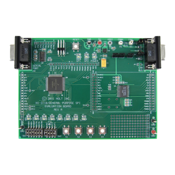
- Page 1 ADK-175 User’s Guide – HI-3110 Evaluation Board April 2020 AN-175 Rev. B Holt Integrated Circuits Arrow.com. Downloaded from...
-
Page 2: Revision History
USB to Serial, External SPI Interface and Two node Rev. A 01-15-13 demonstration. Improve board schematic diagram resolution. Update Freescale Development Tools information. Rev. B 04-20-2020 Update document to new format. Holt Integrated Circuits Arrow.com. Arrow.com. Downloaded from Downloaded from... - Page 3 AN-175 Introduction The Holt HI-3110 ARINC 825 CAN BUS Controller Evaluation Board can be used to evaluate some of the features of the HI-3110 CAN Controller IC with integrated transceiver. A Freescale MC9S12XDT512 microcontroller with 512K flash and 20K RAM communicates with the HI-3110 through the SPI interface.
-
Page 4: Kit Contents
AN-175 KIT CONTENTS This Users Guide. HI-3110 Evaluation Board HI-3110 Data Sheet RS-232 Serial Cable USB to Serial Adapter Codewarrior™ Demo Software Project Demonstration Features Transmit Modes for Standard and Extended Frames ... -
Page 5: Demonstration Set-Up
The purpose of this MRST dip switch is to allow easy interfacing of an external MCU to the HI-3110 such that the SPI signals from the Freescale MCU will be forced into high impedance so as not to conflict with an external MCU. For normal operation keep this switch open and use the RESET button to reset the MCU during testing. - Page 6 If the data doesn’t match the expected value from the previous transmission it will turn on the Red LED8 and halt. Transmitter Modes: If OPT1 is in the open position a 400us delay will be inserted between each transmission. Holt Integrated Circuits Arrow.com. Arrow.com. Arrow.com.
- Page 7 Sleep Mode status Serial Commands Menu A simple menu of commands is provided for resetting the HI-3110, reading and displaying the HI-3110 status registers, and a demo how to pass input strings to the program. There are provisions for additional user code to be implemented so custom commands can be developed and easily integrated.
-
Page 8: Board Jumpers
Using the HI-3110 with an external MCU or FPGA To use the HI-3110 with an external MCU or FPGA close the RESET DIP switch 4 in SW2. This will hold the Freescale MCU in the reset state and keep the SPI signals from the Freescale MCU in tri-state. This allows the SPI signals to be driven by an external source without having to remove the Freescale MCU on the board. - Page 9 LED1-4 will reflect the lower nibble of byte3 of the data-field. CAN Error Detection While receiving frames if there are any errors detected in the HI-3110 registers, TEC, REC or ERR, they will be automatically logged on the Serial Port.
- Page 10 Normal Mode Resumed from Monitor Mode REC: 01 ERR: 04 The last line shows a BUS error that was caused when the HI-3110 was in Sleep Mode and woke up due to a CAN message coming in. Holt Integrated Circuits Arrow.com.
- Page 11 Monitor mode is a simple version similar to Receive mode but just captures the CAN data without providing an acknowledge bit on the Bus. Press Button-1 to stop receiving CAN messages and print the last 64 CAN frames and the HI-3110 status registers on the serial console.
- Page 12 This is very similar to normal Receive mode-2 but without Sleep Mode. The main purpose is to demonstrate how to use interrupts to received the CAN Bus data in the background. Press Button-1 to stop receiving CAN messages and print the last 64 CAN frames and the HI-3110 status registers on the serial console.
- Page 13 ************** HOLT HI-3110 Serial Console Commands Input String Demo Reset Status Register Read Filter Incrementing Enter Selection:2 Enter “1” to generate a hardware reset to the HI-3110. Enter “2” for the status register read and display: CTR0 =80 CTR1 =00 BTR0 =00 BTR1 =00...
-
Page 14: Software Description
32K code size. The current code size is approximately 10.5K. The main functions are in main.c and the lower level HI-3110 drivers are in the 3110Driver.c file. Some program flow charts are provided to help clarify some of the program. - Page 15 GPIO interrupts Initilize Timer0 periodic interrupt 100us Display program revision on LEDs Turn off all LEDs Display header message on the serial console Generate a hardware reset to the HI-3110 Read Option Switches Read Mode switches Test Mode? Test Mode...
- Page 16 For Modes 1, 5 PortP_ISR and 6 PP2 GP2 Pin? Fetch RX FIFO Data Set Ready Flag Clear Interrupt PP3 GP1 Pin? Set G_TCPLTIE Flg Clear Interrupt return Holt Integrated Circuits Arrow.com. Arrow.com. Arrow.com. Arrow.com. Arrow.com. Arrow.com. Arrow.com. Arrow.com. Arrow.com. Arrow.com.
- Page 17 32-bit counter compare? OPT1 switch open? Turn on RED LED8 and Halt Increment 32-bit counter Increment message count Message count Reset Message = 64? count to 0 Holt Integrated Circuits Arrow.com. Arrow.com. Arrow.com. Arrow.com. Arrow.com. Arrow.com. Arrow.com. Arrow.com. Arrow.com. Arrow.com. Arrow.com.
- Page 18 Print History SW3 button pushed? FIFO Load 8 Std or Ext Frames into FIFO Wait for TXCPLT FIFO Empty? OPT1 SW Wait 100us open? Holt Integrated Circuits Arrow.com. Arrow.com. Arrow.com. Arrow.com. Arrow.com. Arrow.com. Arrow.com. Arrow.com. Arrow.com. Arrow.com. Arrow.com. Arrow.com.
- Page 19 A one second interrupt handler in the TIMER_ISR is provided. Any code placed here will automatically get executed every second. if (!count100us) // 1 second scheduler count100us = K_1SEC; if(ON==g_ledFlashBool) // Flash the LED8 ^= TOGGLE; // Alive 1 second blink Holt Integrated Circuits Arrow.com. Arrow.com. Arrow.com. Arrow.com. Arrow.com. Arrow.com. Arrow.com. Arrow.com.
- Page 20 AN-175 HI-3110 Interrupts The HI-3110 can be configured to output status on the INT, STAT, GP1 and GP2 pins which connect to the MCU PP0 – PP3 inputs. Interrupt handlers are provided for the GP1 and GP1 for servicing TXCPLT and RXFIFO respectively on the PP3 and PP2 pins which are enabled by calling PortP_Int().
- Page 21 Al l the other functions in this module are based on and utilize these basic functions. Init3110() This function is provided to initialize the HI-3110 for the desired mode and bit rate. uint8 Init3110(const mode, uint8 ttdiv, uint8 wakeup, uint8 reset, uint8 bor) See the 3110Driver.h header file for the options available in the define statements.
-
Page 22: Transmit Mode
Select transmit mode from the SW1 dip switches and Press Button-1 after a POR to start transmitting frames. The transmit function configures the HI-3110 for normal mode at the CAN Bus rate according to the Bit Rate dip switches. A frame is composed of a predefined header “T8Header[]” and eight bytes for the data-field. - Page 23 All other messages other than 0x47 will be except by filter-3. Refer to the datasheet page 38 and example code for the bit assignments of the other 5 bytes in these arrays. Holt Integrated Circuits Arrow.com. Arrow.com.
- Page 24 The USB debugger tool used on Holt demo boards supporting the Freescale MC9S12XD processor family for PE Micro USB debugger tool is now obsolete. Some Holt documents may still refer to the old debugger shown below: PN USBMULTILINKBDME A suitable replacement is the PE Micro USB Multilink Universal.
- Page 25 Holt HI-3110 project loaded with Codewarrior 5.9.0 SUMMARY This Users Guide explains the features and capabilities of the HI-3110 demo software. To learn more about the HI-3110 refer to the HI-3110 data sheet. This document and the demo software project are included on the CD-ROM. References: http://www.holtic.com/...
- Page 26 Bill of Materials HI-3110 Evaluation Board PCB Rev-2 Item Description Reference DigiKey PCB, Bare, Evaluation Board -------- RS-232 Serial Cable Separated ordering AE1379-ND Capacitor, Cer 10pF 50V 5% NP0 0805 C11,C12,C15,C19 399-1108-1-ND Capacitor, Cer 470pF 50V 5% X7R 0805 399-1133-1-ND...
- Page 27 Arrow.com. Arrow.com. Arrow.com. Arrow.com. Arrow.com. Arrow.com. Arrow.com. Arrow.com. Arrow.com. Arrow.com. Arrow.com. Arrow.com. Arrow.com. Arrow.com. Arrow.com. Arrow.com. Arrow.com. Arrow.com. Arrow.com. Arrow.com. Arrow.com. Arrow.com. Arrow.com. Arrow.com. Arrow.com. Arrow.com. Arrow.com. Downloaded from Downloaded from Downloaded from Downloaded from Downloaded from Downloaded from Downloaded from Downloaded from Downloaded from Downloaded from...
Need help?
Do you have a question about the HI-3110 and is the answer not in the manual?
Questions and answers