
Related Manuals for SCANCLIMBER SC4000

Summary of Contents for SCANCLIMBER SC4000
- Page 1 SC4000 20-140295-1-2 INSTRUCTION MANUAL SC4000 SERIAL NO:________ SCANCLIMBER OY • Turkkirata 26 • FI-33960 PIRKKALA, FINLAND • • Tel. +358 10 680 7000 • Fax +358 10 680 7033 • www.scanclimber.com V23C_09.13...
-
Page 3: Table Of Contents
CONTENTS GENERAL INFORMATION ..............3 1.1. General description ................3 1.2. Basic delivery scope of SC4000 on wheel chassis with 12.5m platform ....................8 1.3. Warranty terms ..................11 TECHNICAL INFORMATION AND ELEC TRIC CHARTS ......3 2.1. Technical specifications ............... 3 2.2. - Page 4 CONTENTS 5.3 2. Transfer with chassis drive unit ............10 5.3 3. Safety harness..................12 5.4. Daily inspections ................. 13 5.5. Functional troubles ................14 SERVICE INSTRUCTIONS ................3 6.1. Platform maintenance ................3 6.2. Inspections ....................4 6.2.1. Daily inspection ..................4 6.2.2.
- Page 5 This document is the instruction manual for Scanclimber SC4000 mast climbing work platform. This is a copy of the original instructions in English. These instructions are made according to Directive 2006/42/EC on machinery and the European standard EN1495 + A2.
- Page 7 1. GENERAL INFORMATION GENERAL INFORMATION ......... 3 1.1. GENERAL DESCRIPTION ........... 3 1.2. BASIC DELIVERY SCOPE OF SC4000 ON WHEEL CHASSIS WITH 12.5 M PLATFORM ....8 1.3. WARRANTY TERMS..........11 General information V23C_09.13 SC4000 Pos 1...
- Page 8 SC4000 Pos 1 V23C_09.13 General information...
-
Page 9: General Information
SCANCLIMBER SC4000 can be used dur SCANCLIMBER SC4000 consists of chas ing all kind of works: assembly, fin ishing, sis, mast and platform sections which are cladding and painting of buildings, fa... - Page 10 Chas sis drive unit is available for the wheel chassis to make the movements at worksite easier. Towing of the SCANCLIMBER SC4000 at work site is possible with a tow bar. !! IT IS NOT AL-...
- Page 11 By connecting two SC4000 SINGLES to gether with platform hinged joints you will get a SC5000 TWIN with wider and more effecient working area. 4002951051 Drawing 1.3. SC4000 twin on minichassis. 40029585K Drawing 1.4. SC4000 twin on wheel chassis. General information V23C_09.13 SC4000 Pos 1...
- Page 12 Drawing 1.5 SC4000 single with di mensions. All outriggers turned out and extended. FREESTANDING HEIGHT 15 M 20029522 Drawing 1.6 SC4000 single with di mensions. All outriggers extended, turned out on mast side only. SC4000 Pos 1 V23C_09.13 General information...
- Page 13 2002951021 Drawing 1.7. SC4000 single on minichassis. Minichassis with dimensions. General information V23C_09.13 SC4000 Pos 1...
-
Page 14: Basic Delivery Scope Of Sc4000 On Wheel Chassis With 12.5M Platform
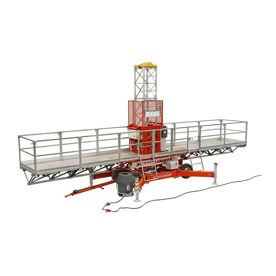
1.2. BASIC DELIVERY SCOPE OF SC4000 ON WHEEL CHASSIS WITH 12.5 M PLATFORM (SEE PICTURE NO. 20-140295-1) item description Wheel chassis Telescopic outrigger with levelling jack Centre jack Ground plate Tow bar Chassis drive unit Cable tray Lifting frame Mast section... - Page 15 2010981E Drawing 1.8. SC4000 single on wheel chassis with 12,5 m platform basic delivery scope. General information V23C_09.13 SC4000 Pos 1...
- Page 16 TABLE OF PART QUANTITIES, WHICH DEPEND ON LIFTING HEIGHT Parts and units, quantity of which de pends on the lifting height are specified in the following table. Quantity in brackets is for SC4000 TWIN. Hoisting platform below 100 m No. Part Drawing...
-
Page 17: Warranty Terms
SCANCLIMBER OY • Turkkirata 26 • FI-33960 PIRKKALA, FINLAND • • Tel. +358 10 680 7000 • Fax +358 10 680 7033 • www.scanclimber.com The warranty liability is limited, at the sellers discretion to replacing the damaged part or... - Page 18 SC4000 Pos 1 V23C_09.13 General information...
- Page 19 2.2.3..MAST ASSEMBLY CRANE .........12 2.2.4..CHASSIS DRIVE UNIT ........13 2.2.5..CENTRE JACK ..........14 2.2.6 ... WEATHER COVER ..........15 2.2.7..WALL ANCHORING .........15 2.3. ELECTRICAL INSTALLATION .........16 2.4. REQUIREMENTS FOR THE SUPPLY VOLTAGE ..17 Technical information SC4000 Pos 2 V23C_09.13...
-
Page 20: Technical Information
Technical information V23C_09.13 SC4000 Pos 2... -
Page 21: Technical Specifications
2. TECHNICAL INFORMATION AND ELECTRICAL DIAGRAMS 2.1. TECHNICAL SPECI FI CATIONS 20-140295-1-1 Drawing 2.1. SC4000 single freestanding with dimensions. 40-1298-85-K-M Drawing 2.2. SC4000 twin freestanding with dimensions. Technical information V23C_09.13 SC4000 Pos 2... - Page 22 Drawing 2.3. Universal wheel chassis with dimensions, X-position Drawing 2.4. Universal wheel chassis with dimensions, K-position Technical information V23C_09.13 SC4000 Pos 2...
- Page 23 0,7x0,7x1,25 0,7x0,7x1,25 weight • Lifting case (fully equipped) l x w x h m 1,5x0,95x0,95 1,5x0,95x0,95 weight 1410 2 x 1410 • Chassis with outriggers l x w 4,95x1,98 4,95x1,98 weight 1710 2 x 1710 Technical information V23C_09.13 SC4000 Pos 2...
- Page 24 Safety sensor during erection • Chassis drive interlocking limit switch • Mast guard nets • Safety railing (height 1,10 m) and toeboards • Automatic platform level control system on twin mast version • Emergency lowering system Technical information SC4000 Pos 2 V23C_09.13...
- Page 25 WEIGHTS OF THE MAIN COMPONETS FOR SC4000 SINGLE AND TWIN COMPONENT NAME Wheel chassis with outriggers and jacks 1710 Chassis drive unit Tow bar for wheel chassis Minichassis Jack Lifting frame - SC4000 steel frame - fully equipped 1410 Mast section...
-
Page 26: Optional Equipment
15. Assemble the bottom fastening piece of the signalling bar. WARNING ! TIGHTEN THE LIFTING CA BLES PROPERLY TO PREVENT PLATFORM FROM FALLING WHEN THE MAST SCREWS ARE LOOSED. Drawing 2.5 Minichassis with di mensions. Technical information SC4000 Pos 2 V23C_09.13... -
Page 27: Telescopic Extensions
THE LOAD ON THE TEL ESCOPIC EXTENSION RE SPEC TIVELY RE DUCES THE MAX. LOAD CARRYING CAPACITY OF THE PLAT FORM. USE RAILINGS. *) ATTENTION ! BEFORE FIXING THE EXTENSION GET ACQUAINTED WITH THE LOADING TA- BLES! Drawing 2.6. Loading table for tel escopic ex tensions. Technical information V23C_09.13 SC4000 Pos 2... - Page 28 The extension tube platform. is situated inside the guiding tube and In pictures the extensions for SC4000 will can be pulled out and locked to desired be described. According to the total length. The railing tube should be locked length of the platform the extensions are to ex tension tube.
- Page 29 20-0594-293-1 20-0594-294-1 Drawing 2.8. SC4000 with telescopic extensions. Technical information SC4000 Pos 2 V23C_09.13...
-
Page 30: Mast Assembly Crane
The vertical part 1 of the assembly crane has to be locked so, that the horizontal part 2 of the assembly crane does not touch the mast when the platform is mov- ing up and down. Technical information V23C_09.13 SC4000 Pos 2... -
Page 31: Chassis Drive Unit
Drawing 2.11. Chassis drive unit and po sitions of the clutch lever. The unit consists of two main parts; the gearmotor and the chain drive. It makes the horizontal movements of SC4000 WARNING: easier. Driving speed is 13 m/min. AFTER RELEASING THE... -
Page 32: Centre Jack
2.2.5. CENTRE JACK Drawing 2.12. Centre jack. NOTE! ALWAYS USE CENTRE JACK. Technical information V23C_09.13 SC4000 Pos 2... -
Page 33: Weather Cover
(wind speed < 12,7 m/s). MAST PLATFORM LENGTH HEIGHT SINGLE 10,5 m 10 m TWIN 18,3 m 10 m 2.2.7. WALL ANCHORING Standard anchor Top anchor Vertically adjustable anchor (See the Wall anchoring instructions chapter 4.) Maxianchor Technical information V23C_09.13 SC4000 Pos 2... -
Page 34: Electrical Installation
OUT OF THE SOCK ETS (E1 AND E2) the safety sensor (B2) is activated by the AND THE HOOTER (H2). sig nalling bar at adjusted height. Socked circuit for hand tools Technical information SC4000 Pos 2 V23C_09.13... -
Page 35: Requirements For The Supply Voltage
= supply cable length +cable con- 5 x 6 mm (min) - Supply ca ble necting the chassis and platform. !!! PAY ATTENTION TO THE LENGTH OF THE SUPPLY CA BLE => VOLTAGE DROP Technical information SC4000 Pos 2 V23C_09.13... - Page 36 Technical information SC4000 Pos 2 V23C_09.13...
- Page 37 3. SAFETY REGULATIONS SAFETY REGULATIONS AND LOADING TABLES ..3 3.1. NOTES ...............3 3.2. SAFETY RULES ............3 3.3. LOADING TABLES SC4000 SIN GLE ......5 3.4. LOADING TABLES SC4000 TWIN ......16 3.5. INSTRUCTION AND WARNING LABELS ON THE MACHINE ...........22 V23C_09.13 SC4000 Pos 3...
- Page 38 SC4000 Pos 3 Safety regulations V23C_09.13...
-
Page 39: Safety Regulations And Loading Tables
7. It is forbidden to let the persons who quirements for working at heights. are not in good physical or mental V23C_09.13 SC4000 Pos 3 Safety regulations... - Page 40 OTHERWISE CAREFULLY SECURED per sonnel only. During those ac THAT THE EN ER GIZED POINTS WILL tions the plat form has to be sup NOT BE TOUCHED. ported and the main current dis connected. SC4000 Pos 3 Safety regulations V23C_09.13...
-
Page 41: Loading Tables Sc4000 Single
3.3. LOADING TABLES SC4000 SIN GLE BEFORE STARTING TO WORK WITH THE MACHINE ALWAYS GET ACQUAINTED WITH THE LOADING TABLES!! The most usual loading variations are shown on the loading tables. There you can find the maximum wind speeds too. If other variations than those shown on the loading tables are needed, please contact the distributor. - Page 42 PLATFORM LOADINGS ON WHEEL CHASSIS MAX. WIND SPEED 15,5 m/s MAX. ALDECK LOADING 150 kg/m LOAD MUST BE EVENLY DISTRIBUTED MAST ANCHORED 900 kg 1200 kg 1400 kg 1700 kg 2000 kg Mpi 950505 VS440281 SC4000 Pos 3 Safety regulations V23C_09.13...
- Page 43 PLATFORM LOADINGS ON MINICHASSIS MAX. WIND SPEED 15,5 m/s MAX. ALDECK LOADING 150 LOAD MUST BE EVENLY DISTRIBUTED 900 kg 1200 kg 1400 kg 1700 kg 2000kg Mpi 950504 VS440282 V23C_09.13 SC4000 Pos 3 Safety regulations...
- Page 44 SIDE TURNED OUT. JACKS SCREWED DOWN. LOAD P=2000 kg HEIGHT H=20 m LENGTH L=4,2 m WIDTH B=1,6 m OUTRIGGERS ON BOTH SIDES EXTENDED AND MAST SIDE TURNED OUT, JACKS Vto 950504 SCREWED DOWN. VS401257 SC4000 Pos 3 Safety regulations V23C_09.13...
- Page 45 P=1400 HEIGHT H=15 LENGTH L=9/7,4 m WIDTH B=1,6 SIDE PLATFORM WIDTH b=1,6 OUTRIGGERS NOT EXTENDED, ON BOTH SIDES TURNED OUT. JACKS SCREWED DOWN. 1400 kg 1400 kg 1400 kg 1400 kg Vto 950420 VS401258 V23C_09.13 SC4000 Pos 3 Safety regulations...
- Page 46 JACKS SCREWED DOWN. LOAD P=1200 HEIGHT H=15 m LENGTH L=7,4 m WIDTH B=1,6 m TELESCOPIC EXTENSION b=1,4 m 1200 kg OUTRIGGERS NOT EXTENDED, ON BOTH SIDES TURNED OUT. JACKS SCREWED DOWN. Vto 950420 VS401259 SC4000 Pos 3 Safety regulations V23C_09.13...
- Page 47 MAST SIDE TURNED OUT. 1200 kg JACKS SCREWED DOWN. LOAD P=900 HEIGHT H=25 m LENGTH L=13,75 m WIDTH B=1,6 m ALL OUTRIGGERS EXTENDED AND ON 900 kg MAST SIDE TURNED OUT. Mpi 950504 JACKS SCREWED DOWN. VS440276 V23C_09.13 SC4000 Pos 3 Safety regulations...
- Page 48 WIDTH B=1,6 m SIDE PLATFORM b=1,6 m WALL ANCHORING ACCORDING TO INSTRUCTIONS. OUTRIGGERS NOT EXTENDED. ON BOTH SIDES TURNED OUT. JACKS SCREWED DOWN. 1400 kg 1400 kg 1400 kg 1400 kg Mpi 950504 VS440278 SC4000 Pos 3 Safety regulations V23C_09.13...
- Page 49 MAX. WIND SPEED 15,5 m/s LOAD MUST BE EVENLY DISTRIBUTED LOAD P=1400 HEIGHT H=100 m LENGTH L=9/7,4 m WIDTH B=1,6 m SIDE PLATFORM b=1,6 OUTRIGGERS ON BOTH SIDES LONGITUDALLY EXTENDED. JACKS SCREWED DOWN. Mpi 950504 VS440279 V23C_09.13 SC4000 Pos 3 Safety regulations...
- Page 50 MAX 100 kg PLYWOOD 22 mm 1680 mm MAX. 1400 mm PLATFORM TELESCOPIC EXTENSION Mpi950424 VS440280 THE LOAD ON THE TELESCOPIC EXTENSION RESPECTIVELY REDUCES THE MAX. LOAD CARRYING CAPACITY OF THE PLATFORM. USE RAILINGS. SC4000 Pos 3 Safety regulations V23C_09.13...
- Page 51 6.1 ALUMINIUM TELESCOPIC EXTENSION 2,2 3,7 m 0,6 m 1,4 m 12,5 m V23C_09.13 SC4000 Pos 3 Safety regulations...
-
Page 52: Loading Tables Sc4000 Twin
3.4 LOADING TABLES SC4000 TWIN BEFORE STARTING TO WORK WITH THE MACHINE ALWAYS GET AC QUAINTED WITH THE LOADING TA BLES!! The most usual loading variations are shown on the loading tables. There you can find the maximum wind speeds too. If other variations than those shown on the loading tables are needed, please contact the distributor. - Page 53 NOTE: ALWAYS WHEN IT IS POSSIBLE, IT IS GOOD TO EXTEND THE OUTRIGGERS. MAX 4200 kg/11.9 m MAX 4050 kg/13.5 m MAX 3800 kg/15.1 m MAX 3500 kg/18.3 m MAX 3250 kg/19.9 m MAX 3020 kg/21.5 m Vto 9500504 VS401260 V23C_09.13 SC4000 Pos 3 Safety regulations...
- Page 54 NOTE: ALWAYS WHEN IT IS POSSIBLE, IT IS GOOD TO EXTEND THE OUTRIGGERS. MAX. 2775 kg/23,1 m MAX. 2680 kg/24,7 m MAX. 2515 kg/26,3 m MAX. 2330 kg/27,9 m MAX. 2165 kg/29,5 m MAX. 2065 kg/31,4 m Vto 950504 VS401261 SC4000 Pos 3 Safety regulations V23C_09.13...
- Page 55 JACKS SCREWED DOWN. NOTE: ALWAYS WHEN IT IS POSSIBLE, IT IS GOOD TO EXTEND THE OUTRIGGERS. MAX 3600 kg/11.9 m MAX 3330 kg/13.5 m MAX 3000 kg/15.1 m MAX 2520 kg/18.3 m MPi950425 VS440284 V23C_09.13 SC4000 Pos 3 Safety regulations...
- Page 56 MAX 4200 /11.9 m MAX 4050 /13.5 m MAX 3800 /15.1 m MAX 3500 /18.3 m MAX 3250 /19.9 m MAX 3020 /21.5 m MAX 2775 /23.1 m MAX 2680 /24.7 m Mpi 950425 VS440285 SC4000 Pos 3 Safety regulations V23C_09.13...
- Page 57 MAX. 3800 kg/15,1 m MAX. 3500 kg/18,3 m MAX. 3250 kg/19,9 m MAX. 3020 kg/21,5 m MAX. 2775 kg/23,1 m MAX. 2680 kg/24,7 m MAX. 2165 /29,5 m MAX. 2065 /31,4 m Vto 950504 VS401262 V23C_09.13 SC4000 Pos 3 Safety regulations...
- Page 58 Ta154 Phase inverter 61155 Ta155 Wheel chassis 61166 Ta166 Caution Platform loadings, twin 61180 Ta120 Warning Emergency lowering Ta196 Aluminium telescopic extension 2,2 3,7 m T_197 Aluminium telescopic extension 2,2 3,7 m SC4000 Pos 3 Safety regulations V23C_09.13...
- Page 59 THE LOCATION OF THE INSTRUCTION AND WARNING STICKERS ON 4000 UNIT T_139 T_137 T_138 T 128 T 129 T 105 T 121 T 122 T 150 T 123 +OP1 T 125 Chassis electric box. V23C_09.13 SC4000 Pos 3 Safety regulations...
- Page 60 V01 V04 Ta118 Ta101 Ta155 Ta149 Ta103 Ta153 Ta106 Ta108 Ta110 Ta148 Ta120 T 142 T 124 +OP2 T 122 T 144 9999h T 121 T 154 T 127 T 125 Platform electric box. SC4000 Pos 3 Safety regulations V23C_09.13...
- Page 61 THE LOCATION OF THE INSTRUCTION AND WARNING STICKERS ON 4000 UNIT V01 0003961935 V23C_09.13 SC4000 Pos 3 Safety regulations...
- Page 62 Ta101 Ta105 SC4000 Pos 3 Safety regulations V23C_09.13...
- Page 63 V23C_09.13 SC4000 Pos 3 Safety regulations...
- Page 64 SC4000 Pos 3 Safety regulations V23C_09.13...
- Page 65 Ta108 V23C_09.13 SC4000 Pos 3 Safety regulations...
- Page 66 Ta110 SC4000 Pos 3 Safety regulations V23C_09.13...
- Page 67 V23C_09.13 SC4000 Pos 3 Safety regulations...
- Page 68 SC4000 Pos 3 Safety regulations V23C_09.13...
- Page 69 V23C_09.13 SC4000 Pos 3 Safety regulations...
- Page 70 Ta137 Ta138 Ta139 SC4000 Pos 3 Safety regulations V23C_09.13...
- Page 71 V23C_09.13 SC4000 Pos 3 Safety regulations...
- Page 72 SC4000 Pos 3 Safety regulations V23C_09.13...
- Page 73 V23C_09.13 SC4000 Pos 3 Safety regulations...
- Page 74 SC4000 Pos 3 Safety regulations V23C_09.13...
- Page 75 V23C_09.13 SC4000 Pos 3 Safety regulations...
- Page 76 SC4000 Pos 3 Safety regulations V23C_09.13...
- Page 77 ALUMINIUM TELESCOPIC EXTENSION 2,2 3,7 m Ta196 T_197 V23C_09.13 SC4000 Pos 3 Safety regulations...
- Page 78 SC4000 Pos 3 Safety regulations V23C_09.13...
- Page 79 4.5. WALL ANCHORING INSTRUCTIONS .......6 4.6. ASSEMBLY IN STRUCTIONS ........17 4.6.1. SC4000 SINGLE ............17 4.6.2. SC4000 TWIN............28 4.6.2.1 CONNECTION BOLTS OF THE PLAT FORM SEC- TIONS BY LONG PLATFORMS IN TWIN UNITS ..39 4.6.3 ASSEMBLY OF THE TELESCOPIC EXTENSIONS ..41 4.7.
- Page 80 SC4000 Pos 4 V23C_09.13 ERECTION AND DISMANTLING...
-
Page 81: Erection And Dismantling
4. ERECTION AND DISMANTLING 4.1. INTRODUCTORY NOTES SC4000 mast climbing work platform has been designed with intention of its easy and quick assembly. Partial assem bly, that should be checked before taking the Scanclimber into use: 1. the assembly of the chassis 2. -
Page 82: Tightening Torques For Screws And Nuts
M16 x 40-8.8 screws connecting lifting gear to the assembly plate M18 -10.9 screws connecting the platforms to each other M14 x 1,25 wheel bolts SC4000 Pos 4 V23C_09.13 ERECTION AND DISMANTLING... -
Page 83: Preparatory Works
WARNING! The tightening torque for all screws in section joints is 350 Nm. Check the torque of the screw connections before bolting on the next mast. V23C_09.13 SC4000 Pos 4 ERECTION AND DISMANTLING... -
Page 84: Wall Anchoring Instructions
See the figures of A/B and F1/F2 on the of the builder, has to be con sid table 20-0895-1206. ered. Drawing 4.1. Anchoring forces. SC4000 Pos 4 V23C_09.13 ERECTION AND DISMANTLING... - Page 85 THE WALL ANCHORAGE ALL OUTRIGGERS FULLY EXTENDED AND OPPOSITE TO THE MAST ALSO TURNED OUT. SC1300: USE MIDDLE JACK WHEN MAST SC4000: USE ALWAYS MIDDLE JACK HEIGHT OVER 30 m VS440230 Drawing 4.2. Wall anchorage instructions for wheel chassis. V23C_09.13...
- Page 86 MAX. ALLOWED PLATFORM LENGTH 4,2 m DURING ERECTION AND DISMANTLING OF THE MAST AND WIND SPEED UNDER 8 M/S. MAX. ALLOWED PLATFORM LENGTH WHEN OPERATING - SC1300 10,5 m - SC4000 12,5 m MAX. ALLOWED WIND SPEED 15,5 m/s SECTION A -A PLATFORM MIN. 150 mm NOTE! CHECK THE STRENGTH OF THE WALL ANCHORAGE.
- Page 87 WHEN ERECTING AND DISMANTLING THE MAST - BENEATH THE 3RD ANCHOR 4,20 m - ABOVE THE 3RD ANCHOR 10,50 m (SC1300) 12,50 m (SC4000) MAX.ALLOWED WIND SPEED15,5 m/s SECTION A-A PLATFORM MIN. 150 MM NOTE! CHECK THE STRENGTH OF THE WALL ANCHORAGE.
- Page 88 ANCHOR FORCES SC4000 WITH 12,5 m PLATFORM MAX. WIND SPEED 15,5 m/s MAX. 3 PERSONS ON THE PLATFORM WITH TOP ANCHOR 20-0895-1206 FORCE F2 WITH DIFFERENT A AND B VALUES A and B mm N (1N = 0.1kp) 1050 1200 1350...
- Page 89 ANCHOR FORCES SC4000 WITH 13,75 m PLATFORM MAX. WIND SPEED 15,5 m/s MAX. 3 PERSONS ON THE PLATFORM WITH TOP ANCHOR 20-0895-1206 FORCE F2 WITH DIFFERENT A AND B VALUES A and B mm N (1N = 0.1kp) 1050 1200 1350...
- Page 90 M OR OTHER WIND SPEEDS CAN BE FOUND FROM FOR- MULA: = (AD/12,5) x (W/42) x F table WHERE: AD = ANCHORING DISTANCE METRES = WIND SPEED M/S 00-0895-1207 = FORCE FROM TABLE table SC4000 Pos 4 V23C_09.13 ERECTION AND DISMANTLING...
- Page 91 FORCES WITH ANCHORING DISTANCES LESS THAN 12.5 M OR OTHER WIND SPEEDS CAN BE FOUND FROM FORMULA: = (AD/12,5) x (W/42) x F table WHERE: AD = ANCHORING DISTANCE METRES 00-0895-1208 = WIND SPEED M/S = FORCE FROM TABLE table V23C_09.13 SC4000 Pos 4 ERECTION AND DISMANTLING...
- Page 92 FORCES WITH ANCHORING DISTANCES LESS THAN 12.5 M OR OTHER WIND SPEEDS CAN BE FOUND FROM FORMULA: = (AD/12,5) x (W/42) x F table WHERE: AD = ANCHORING DISTANCE METRES 00-0895-1208 = WIND SPEED M/S = FORCE FROM TABLE table SC4000 Pos 4 V23C_09.13 ERECTION AND DISMANTLING...
- Page 93 Drawing 4.5. Standard anchoring. 00-0994-51-1 00-0994-53-1 Drawing 4.6. Vertically adjustable anchoring. V23C_09.13 SC4000 Pos 4 ERECTION AND DISMANTLING...
- Page 94 5.5 kN, when a swivel coupler is used in diagonal. Picture below describes the anchoring code PG100166. Anch2 Anch1 ☞ If load is too big for anchoring, can double anchoring be used. In this case results are divided by 1,5. SC4000 Pos 4 V23C_09.13 ERECTION AND DISMANTLING...
-
Page 95: Assembly Instructions
4.6. ASSEMBLY IN STRUCTIONS NOTE! DURING ASSEMBLY DO NOT FORGET TO FILL IN THE ERECTION FORM (CHAP TER 10). Drawing 4.8. SC4000 single. 20-0295-106-5-2 2A. Freestanding 4.6.1. SC4000 SINGLE Max. lifting height/platform length: Partly assembled platform should 15/12,5 m. be erected on well prepared base Max. - Page 96 20-140295-1-2 Drawing 4.9. SC4000 single - freestanding. 2B. Freestanding Lift the chassis by turning the drive shafts equally so that the tyres do Max. lifting height / platform length: not touch the ground. The distance 15/12,5 m between the tyres and the ground is Max.
- Page 97 LOAD MUST BE EVENLY DISTRIBUTED OUTRIGGERS ON BOTH SIDES MUST BE FULLY TURNED AND PULLED OUT JACK SCREWED DOWN 1400 kg 900 kg 1200 kg 1400 kg 1700 kg 2000 kg Mpi 950504 VS440286 V23C_09.13 SC4000 Pos 4 ERECTION AND DISMANTLING...
- Page 98 MAX. WIND SPEED 12,7 m/s LOAD MUST BE EVENLY DISTRIBUTED ATTENTION! ALL OUTRIGGERS PULLED OUT AND ON MAST SIDE ALSO TURNED JACKS SCREWED DOWN. 900 kg 1200 kg 1400 kg 1700 kg 2000 kg Mpi 950504 VS440283 SC4000 Pos 4 V23C_09.13 ERECTION AND DISMANTLING...
- Page 99 Use only screws de- liv ered by the manu fac turer. Tighten 00-0994-601-1 the screws 195 Nm. ALWAYS MOUNTING SUPPORT UNDER PLATFORM SECTION!! Drawing 4.12. Use of special tool. 00-0994-603-2 V23C_09.13 SC4000 Pos 4 ERECTION AND DISMANTLING...
- Page 100 UP on the pendant con trol and note the movements of the platform. 00-0994-279-1 S4 PUSH-BUTTON - FORWARD/UP S5 PUSH-BUTTON - REWARD/DOWN S6 EMERGENCY STOP Drawing 4.15. Pendant control E3 (hori zon tal/vertical drive). X6 PLUG SC4000 Pos 4 V23C_09.13 ERECTION AND DISMANTLING...
- Page 101 - connect the special plug -X5.1 to the -Q2.1 STOP -XS7 -X8 socket -X5 -X22 option: thermostat Drawing 4.17 Platform driving control realised by the drive buttons located on the platform electric box + OP2 V23C_09.13 SC4000 Pos 4 ERECTION AND DISMANTLING...
- Page 102 = SOCKET FOR GATE = SOCKET FOR TEST XS.1 = SPECIAL PLUG Q2.1 = PHASE INVERTER SWITCH = CONTROL LAMP “PHASES OK” Drawing 4.18 Platform driving control realised by the pendant control box E3 SC4000 Pos 4 V23C_09.13 ERECTION AND DISMANTLING...
- Page 103 0.2 to 0.3 m/s and stops automatically. Drawing 4.19. Safety brake test. 20-1294-287-U V23C_09.13 SC4000 Pos 4 ERECTION AND DISMANTLING...
- Page 104 RESETING THE SAFETY BRAKE Open the safety brake cover (1) with 10 mm wrench. Open the two screws (2) of the bronze nut (3) with 10 mm wrench. SC4000 Pos 4 V23C_09.13 ERECTION AND DISMANTLING...
- Page 105 Rotate the bronze nut (3) by hand to align the two screws. Install the two screws (2). Mount the cover (1) Release the safety brake by lifting the platform. V23C_09.13 SC4000 Pos 4 ERECTION AND DISMANTLING...
-
Page 106: Sc4000 Twin
Erect the masts on well pre pared base at a suitable dis tance of the wall. The suitable distance be tween the machines and the wall is approx. 150-250 mm. 13-0994-103-1 Drawing 4.21. SC4000 twin. SC4000 Pos 4 V23C_09.13 ERECTION AND DISMANTLING... - Page 107 On mast side also turned out and locked with pins (mast side = the side of chassis where the mast is erected). Drawing 4.22. SC4000 twin. 2B. Freestanding Max. lifting height/platform length: 10/31,4 m. Max. wind speed: 12,7 m/s.
- Page 108 PLATFORM IS SURROUNDED BY RAI each other the with help of a spe cial LINGS. LEVEL INDICATOR 30 mm Drawing 4.24. Location of level indicator. Air gap 30 mm. 20-140295-1 Drawing 4.25. Assembly of platform sections. SC4000 Pos 4 V23C_09.13 ERECTION AND DISMANTLING...
- Page 109 Use of special tool. USE ALWAYS MOUNTING SUPPORT UNDER PLATFORM SECTION!! Drawing 4.26. Use of special tool. Drawing 4.27. Assembly of middle platform. V23C_09.13 SC4000 Pos 4 ERECTION AND DISMANTLING...
- Page 110 3. Assemble the steering cable ac- Drawing 4.28. Assembly of the hinge cording to drawing. halves to middle the platform. +OP2 +OP2 ADAPTER ADAPTER Drawing 4.29. Assembly of the steering cable. SC4000 Pos 4 V23C_09.13 ERECTION AND DISMANTLING...
- Page 111 (drawing 4.30) so that the pin on the lever No 3 will fit to the plate opening on the hinge-half of the last mounted middle platform section. V200076 Drawing 4.30. Levelling device levelling rod (4). V23C_09.13 SC4000 Pos 4 ERECTION AND DISMANTLING...
- Page 112 = SOCKET FOR TEST control and note the move ments XS.1 = SPECIAL PLUG of the plat form. Q2.1 = PHASE INVERTER SWITCH = CONTROL LAMP “PHASES OK” Drawing 4.33. Platform electric box. SC4000 Pos 4 V23C_09.13 ERECTION AND DISMANTLING...
- Page 113 (4) in the drawing below so that the V200076 limit switch roller will fit to the hole on the plate (5). Limit switch in 0-posi- tion. Drawing 4.35. Adjustment of the stabilizing mechanism. V23C_09.13 SC4000 Pos 4 ERECTION AND DISMANTLING...
- Page 114 1,5° to re set the platform`s normal con trol i.e. pendant control. 4. Level the platform by using the pendant control 5. Test also the other unit respecti- vely. SC4000 Pos 4 V23C_09.13 ERECTION AND DISMANTLING...
- Page 115 2. and drawing no. 4.36 below). Evacuate the platform during the test. The test is to be carried out by trained or authorized person only. 40-0295-287-2 Drawing 4.36. Safety brake test. +OP2 +OP2 ADAPTER ADAPTER V23C_09.13 SC4000 Pos 4 ERECTION AND DISMANTLING...
- Page 116 This in- spection should be carried out by an authorized inspector. See 4.7. The mast sections can be assem- bled on top of each other by using the mast assembly crane arm (see SC4000 Pos 4 V23C_09.13 ERECTION AND DISMANTLING...
-
Page 117: Connection Bolts Of The Plat Form Sec- Tions By Long Platforms In Twin Units
BY LONG PLATFORMS IN TWIN UNITS 1. If there are eight (8) platform sections in the middle platform, the connec- tion bolts shall be M18 x 240 10.9. M18 x 240 10.9 M18x 240 10.9 Drawing 4.39. V23C_09.13 SC4000 Pos 4 ERECTION AND DISMANTLING... - Page 118 2. If there are nine (9) platform sections in the middle plat form, the connection bolts shall be M18 x 240 10.9. M18 x 240 10.9 M18 x 240 10.9 Drawing 4.40. SC4000 Pos 4 V23C_09.13 ERECTION AND DISMANTLING...
-
Page 119: Assembly Of The Telescopic Extensions
THE RAILING BOARD MUST BE USED IN THE RAILINGS. IN THE ASSEMBLY OF THE TELESCOPIC EXTENSIONS IT IS ALLOWED TO USE ONLY PARTS AND MATERIAL RECOMMENDED BY THE MANU FAC TURER, SEE SECTION 8. V23C_09.13 SC4000 Pos 4 ERECTION AND DISMANTLING... - Page 120 20-1096-2134 Drawing 4.41. Assembly of the tel escopic ex tension. SC4000 Pos 4 V23C_09.13 ERECTION AND DISMANTLING...
- Page 121 ALUMINIUM TELESCOPIC EXTENSION 2,2 3,7 m aluminium telescopic extension,right 2,2 3,7 m aluminium telescopic extension,left 2,2 3,7 m locking pin V23C_09.13 SC4000 Pos 4 ERECTION AND DISMANTLING...
-
Page 122: The Check Of Assembled Platform
Press the emergency stop S6 when driving to any direction and the plat- form should stop immediately. Check the connections of all mast sections, which should be tight ened with a torque of 350 Nm. SC4000 Pos 4 V23C_09.13 ERECTION AND DISMANTLING... - Page 123 Check the functions of the platform. Check the latitude between guiding rollers and mast section pipes. Check the latitude of the rack and the pinion . Check the guiding rollers latitude to the rack. V23C_09.13 SC4000 Pos 4 ERECTION AND DISMANTLING...
-
Page 124: Platform Disassembly
NOTE; WHEN USING MINICHASSIS DO NOT FORGET TO UNLOAD AND SHORTEN THE PLATFORM (MAX. LENGTH OF PLATFORM 4.2 M) BEFORE DISMOUNTING THE THREE LAST WALL ANCHORS! All the dismounted elements should be cleaned, protected and well prepared for transportation. SC4000 Pos 4 V23C_09.13 ERECTION AND DISMANTLING... -
Page 125: Operational Instructions
CONTROL INSTRUCTIONS ........8 5.3.1. .. LIFTING / LOWERING ........8 5.3 2. .. TRANSFER WITH CHASSIS DRIVE UNIT (OPTIONAL EQUIPMENT) ........10 5.3.3 SAFETY HARNESS ..........12 5.4. DAILY INSPECTIONS ......... 13 5.5. FUNCTIONAL TROUBLES ........14 SC4000 Pos 5 V23C_09.13 OPERATIONAL INSTRUCTIONS... - Page 126 SC4000 Pos 5 V23C_09.13 OPERATIONAL INSTRUCTIONS...
-
Page 127: Instructions/Warnings For The Operators
- Do not use faulty machine. - Do not work if your physical condition is not well. - Inform of any suspected faults. - Prevent the unauthorized use of the platform. - Provide adequate lighting for safe operation. SC4000 Pos 5 V23C_09.13 OPERATIONAL INSTRUCTIONS... -
Page 128: Operation Instructions
XS.1 = SPECIAL PLUG - PUSH-BUTTON-REWARD/ DOWN Q2.1 = PHASE INVERTER SWITCH - EMERGENCY STOP = CONTROL LAMP “PHASES OK” - PLUG Drawing 5.3. Pendant control E3 Drawing 5.1. Platform electric box OP2. (horizontal/vertical drive). SC4000 Pos 5 V23C_09.13 OPERATIONAL INSTRUCTIONS... -
Page 129: Scope Of Operator´s Responsibilities
2. meshing of the pinions: driving and After engagement of the safety brake, safety brake with rack, it is necessary to find out the reason be- fore releasing the safety brake. condition of the lifting gear, SC4000 Pos 5 V23C_09.13 OPERATIONAL INSTRUCTIONS... - Page 130 In case to the safety brake is engaged end of platform´s lifting motor. due to damage of bearing element (e.g. pin ion), it is prohibited to release it. In such case following steps should be taken: Drawing 5.4. Emergency-lowering system. SC4000 Pos 5 V23C_09.13 OPERATIONAL INSTRUCTIONS...
- Page 131 - push the yellow button S3 and hold in and remove the reason of operating this position the limit switch. - push the button of going up and leave the zone of operating the limit switch SC4000 Pos 5 V23C_09.13 OPERATIONAL INSTRUCTIONS...
-
Page 132: Control Instructions
- connect the special plug X5.1 to the socket -X5 -Q2.1 STOP -XS7 -X8 -X22 option: thermostat Drawing 5.5 Platform driving control re- alised by the drive buttons located on the platform electric box + OP2 SC4000 Pos 5 V23C_09.13 OPERATIONAL INSTRUCTIONS... - Page 133 - disconnect the supply cable from the socket X1 of the chassis electric box and put it to a safety place (Note: The cable is under tension until the supply cable is disconnected from the wall socket) SC4000 Pos 5 V23C_09.13 OPERATIONAL INSTRUCTIONS...
-
Page 134: Transfer With Chassis Drive Unit
• Turn the outriggers out. • Lower the jacks. • The lower safety limit shall be by- passed when lifting the platform from rubber buffers. The bypass switch is in the platform electric box. SC4000 Pos 5 V23C_09.13 OPERATIONAL INSTRUCTIONS... - Page 135 The lower safety limit is bypassed pushing a bypass button on the platform electric box and pushing simultaneously up-button. Before bypassing the limit switch it must be settled out why the platform has reached the safety limit! +OP2 SC4000 Pos 5 V23C_09.13 OPERATIONAL INSTRUCTIONS...
-
Page 136: Safety Harness
250 mm and the platform is not fully rounded with railing. The safety harness is fastened to the hook on the top frame or platform sec- tion. SC4000 Pos 5 V23C_09.13 OPERATIONAL INSTRUCTIONS... -
Page 137: Daily Inspections
14. Check the wall anchoring. 15. Check the mast guards. 16. Checkthe loose or missing parts. 17. Check that worksite is safety fenced. 18. Check the warning and instruction plates. 19. Check the working area. SC4000 Pos 5 V23C_09.13 OPERATIONAL INSTRUCTIONS... -
Page 138: Functional Troubles
Q1.1 5. phase is missing check the condition of the supply ca ble and fuses.* 6. ”emergency stop” release ”emergency stop” - switch down - switch 7. protective earthing check that the supply SC4000 Pos 5 V23C_09.13 OPERATIONAL INSTRUCTIONS... - Page 139 S11* down but not broken or stuck (call maintenance techni- cian) 2. inductive limit B1 broken change inductive limit B1* (call maintenance techni- cian) 3. push-button S4 broken change pendant con trol SC4000 Pos 5 V23C_09.13 OPERATIONAL INSTRUCTIONS...
- Page 140 + the cable length from 400 V - 20 V =380 V). chassis to the platform). *) NOTE! THE MAIN SWITCH Q1 HAS TO BE SWITCHED TO 0POSITION BEFORE OPENING THE ELECTRIC BOX CENTRE. SC4000 Pos 5 V23C_09.13 OPERATIONAL INSTRUCTIONS...
-
Page 141: Service Instructions
6.3.2. DENOTATION OF OILS AND GREASES USED ..8 6.3.3. LUBRICATION PERIODS ........8 6.3.4. PLATFORM LUBRICATION SCHEDULE ....9 6.4. DRAWINGS ILLUSTRATING THE MEASUREMENTS AND ADJUSTMENT PROCEDURES ...........12 6.4.1. TIGHTENING TORQUES FOR SCREWS AND NUTS ............13 V23C_09.13 SC4000 Pos 6 SERVICE INSTRUCTIONS... - Page 142 SC4000 Pos 6 SERVICE INSTRUCTIONS V23C_09.13...
-
Page 143: Platform Maintenance
FORM OR TWIN PLATFORM, THE MAIN VOLTAGE HAS TO BE SWITCHED OFF WITH THE MAIN SWITCH Q0 AND Q1OR IT HAS TO OTHERWISE BE CAREFULLY SE CURED THAT THE EN ER GIZED POINTS WILL NOT BE TOUCHED. V23C_09.13 SC4000 Pos 6 SERVICE INSTRUCTIONS... -
Page 144: Inspections
14. Check the wall anchoring. 15. Check the mast guards. 16. Check the loose or missing parts. 17. Check that the worksite is safety fenced. 18. Check the warning and instruction plates. 19. Check the working area. SC4000 Pos 6 SERVICE INSTRUCTIONS V23C_09.13... -
Page 145: Frequent Inspections
120 hours of operation. NOTE: DAILY AND WEEKLY INSPECTIONS, POINTS 1-26 SHOULD ALSO BE CARRIED OUT. *) The main switch Q0 and Q1 has to be switched to 0-position before opening the electric centre. V23C_09.13 SC4000 Pos 6 SERVICE INSTRUCTIONS... -
Page 146: Quarter Of A Year Inspection
45. Check that the safety brake is overhauled (must be replaced every 4 years) Drawing 6.5. Frequent inspection form. NOTE: DAILY, WEEKLY, MONTHLY AND QUARTER-OF- A-YEAR IN SPECTIONS, POINTS 1-41 SHOULD ALSO BE CARRIED OUT. SC4000 Pos 6 SERVICE INSTRUCTIONS V23C_09.13... -
Page 147: Lubrication
6.3.1. CAPACITY OF GEAR OIL TANKS Gear of the drive motor RF 73 1,2 l Gear of the lifting motor KF 87 3,7 l Please see the service instructions of manu fac turer (chap ter 9A). V23C_09.13 SC4000 Pos 6 SERVICE INSTRUCTIONS... -
Page 148: Denotation Of Oils And Greases Used
9) 6.3.3. LUBRICATION PERIODS To avoid the operational breaks, it is recommended to observe the following periods for lubrication: 30 h week 120 h month 360 h months 1400 h months SC4000 Pos 6 SERVICE INSTRUCTIONS V23C_09.13... -
Page 149: Platform Lubrication Schedule
V23C_09.13 SC4000 Pos 6 SERVICE INSTRUCTIONS... - Page 150 2+gear gear box of the lifting oil change see boxes motor manufactures service instructions single arm and axles of the smear with machine oil limit switches brush twin bearing of rear the smear with grease axle brush SC4000 Pos 6 SERVICE INSTRUCTIONS V23C_09.13...
- Page 151 LUBRICATION POINTS TWIN - top limit - bottom limit - chassis interlock Graphite grease grease machineoil gear oil (read manufacturer serv ice in structions, chapter 9) V23C_09.13 SC4000 Pos 6 SERVICE INSTRUCTIONS...
-
Page 152: Drawings Illustrating The Measurements And Adjustment Procedures
The eccentric shafts of the guiding rollers will be turned until the right clearance will be reached (1,0). The clearance is meas- ured between the guiding rollers and the mast edge bars. Drawing 6.9. Guiding rollers. SC4000 Pos 6 SERVICE INSTRUCTIONS V23C_09.13... -
Page 153: Tightening Torques For Screws And Nuts
1,0 mm. Drawing 6.11. 6.4.1. TIGHTENING TORQUES FOR SCREWS AND NUTS See table on 4. V23C_09.13 SC4000 Pos 6 SERVICE INSTRUCTIONS... - Page 154 SC4000 Pos 6 SERVICE INSTRUCTIONS V23C_09.13...
-
Page 155: Storage And Transport
7. STORAGE AND TRANSPORT STORAGE AND TRANSPORT........3 7.1..STORAGE INSTRUCTION........3 7.2..TRANSPORT INSTRUCTION........3 V23C_09.13 SC4000 Pos 7 STORAGE AND TRANSPORT... - Page 156 SC4000 Pos 7 V23C_09.13 STORAGE AND TRANSPORT...
- Page 157 7.2. TRANSPORT INSTRUCTION When disassembling SC4000 for transport, don´t forget to lower the platform onto the rubber cushion of the chassis with help of the emer- gency lowering levers at the end of the lifting gear motors.
- Page 158 4 520 kg HEIGHT 2,35 m WIDTH 1,98 m 20-0594-56-2 Drawing 7.2. 2 platform sections. TRANSPORT DIMENSIONS PLATFORM LENGTH WEIGHT LENGTH 5,0 m 4,2 m 3 650 kg HEIGHT 2,35 m WIDTH 1,98 m SC4000 Pos 7 V23C_09.13 STORAGE AND TRANSPORT...
- Page 159 3 750 kg HEIGHT 2,35 m WIDTH 1,98 m 20-0594-58-2 Drawing 7.4. 2 platform sections. TRANSPORT DIMENSIONS PLATFORM LENGTH WEIGHT LENGTH 4,2 m 4,2 m 1 620 kg HEIGHT 2,35 m WIDTH 1,98 m V23C_09.13 SC4000 Pos 7 STORAGE AND TRANSPORT...
- Page 160 SC4000 Pos 7 V23C_09.13 STORAGE AND TRANSPORT...
-
Page 161: Inspection Forms
10. INSPECTION FORMS ERECTION FORM ............... 3 DAILY INSPECTION FORM ..........4 FREQUENT INSPECTION FORM ......... 5 V23C_09.13 SC4000 Pos 10 INSPECTION FORMS... - Page 162 SC4000 SC4000...
-
Page 163: Erection Form
OUTRIGGERS FULLY TURNED, EXTENDED AND LOCKED WITH PIN JACKS SCREWED DOWN AGAINST GROUND PLATES PLATFORM AND MAST ARE VERTICALLY AND HORIZONTALLY ADJUSTED CENTRE JACK: SC4000 ALWAYS, SC1300 MAST HEIGHT > 30M PLYWOOD BOARD ON TELESCOPIC EXTENSIONS (MIN. 22 MM) DISTANCE BETWEEN PLATFORM AND WALL (MANUAL CHAPTER 4.) -
Page 164: Daily Inspection Form
SC4000 SC4000 DAILY INSPECTION FORM WORKSITE:_______________________________________________________________________________ TYPE OF MACHINE:____________________________________________ SERIAL NO:________________ PLATFORM LENGTH:____________________MAX. LIFTING CAPACITY:_________ HEIGHT:__________ ERECTION COMPANY:____________________________________________________________________ PERSON IN CHARGE:___________________________________ __________ TEL.:____________________ ORDER COMPANY:______________________________________________________________________ PERSON IN CHARGE:_____________________________________________ TEL.:____________________ T TEST VISUAL INSPECTION VISUAL INSPECTION NOTE: - FILL UP AND SIGN THIS FORM BEFORE YOU START WORKING WITH THE UNIT... -
Page 165: Frequent Inspection Form
SC4000 SC4000 FREQUENT INSPECTION FORM WORKSITE:_______________________________________________________________________________ TYPE OF MACHINE:____________________________________________ SERIAL NO:________________ PLATFORM LENGTH:____________________MAX. LIFTING CAPACITY:_________ HEIGHT:__________ ERECTION COMPANY:____________________________________________________________________ PERSON IN CHARGE:___________________________________ __________ TEL.:____________________ ORDER COMPANY:______________________________________________________________________ PERSON IN CHARGE:_____________________________________________ TEL.:____________________ = WEEKLY - MARK WITH CROSS CHECKINGS CARRIED OUT = MONTHLY... - Page 166 SC4000 SC4000...
Need help?
Do you have a question about the SC4000 and is the answer not in the manual?
Questions and answers