
Related Manuals for TruVision 6 IP Series


Summary of Contents for TruVision 6 IP Series
- Page 1 TruVision Series 6 IP Camera with Cable Harness Installation Guide P/N 1073701-EN • REV B • ISS 02JUN21...
- Page 3 Safety instructions These instructions are intended to ensure that user can use the product correctly to avoid danger or property loss. The precaution measures are divided into “Warnings” and “Cautions”. Warnings: Warning messages advise you of hazards that could result in injury or loss of life. They tell you which actions to take or to avoid in order to prevent the injury or loss of life.
- Page 4 • Please make sure that the plug is firmly connected to the power socket. When the device is mounted on a wall or ceiling, it should be firmly fixed to the surface. • If smoke, odor or noise rises from the device, turn off the power at once and unplug the power cable.
- Page 5 • To avoid heat accumulation, good ventilation is required for operating environment. • Keep the camera away from liquid while in use. • During delivery, the camera shall be packed in its original packing, or packing of the same texture. •...
-
Page 7: Table Of Contents
Mounting the dome camera 21 Network access 24 Checking your web browser security level 24 Activating the camera 26 Using the camera with a TruVision recorder or another system 29 Using the camera with TruVision Navigator 30 Specifications 30 TruVision IP motorized lens bullet cameras 30... - Page 8 Legal and regulatory information 34 Installation Guide...
-
Page 9: Introduction
Introduction Product overview This is the installation guide for TruVision Series 6 IP Camera with Cable Harness models: TVB-5604H (2MPX IP motorized lens bullet camera) TVB-5605H (4MPX IP motorized lens bullet camera) TVB-5606H (8MPX IP motorized lens bullet camera) ... -
Page 10: Contact Information And Manuals /Tools /Firmware
Contact information and manuals /tools /firmware For contact information and to download the latest manuals, tools, and firmware, go to the web site of your region: EMEA: https://firesecurityproducts.com Handbücher sind in mehreren Sprachen verfügbar. Australien/ https://firesecurityproducts.com.au Neuseeland: Installation Guide... -
Page 11: Installation
Installation This section provides information on how to install the cameras. Before you start: • Make sure the device in the package is in good condition and all the assembly parts are included. • The standard power supply is 12 VDC, PoE (802.3 af) or PoE+ (802.3 at). -
Page 12: Installation Environment
camera body so that the foam ring and the dome cover are attached seamlessly. Installation environment When installing your product, consider these factors: • Electrical: Install electrical wiring carefully. It should be done by qualified service personnel. Always use a proper PoE switch or a 12 VDC UL listed Class 2 or CE certified power supply to power the camera. -
Page 13: Package Contents
ethanol and wipe the camera gently. If the camera will not be used for an extended period of time, put on the lens cap to protect the sensor from dirt. Package contents Check the package and contents for visible damage. If any components are damaged or missing, do not attempt to use the unit;... - Page 14 Screws for the back Torx wrench • • box(4 pcs) Installation guide • G3/4 cable adapter • • Desiccant Equipment disposal • sheet Battery disposal sheet • Installation Guide...
- Page 15 IP motorized lens turret camera Camera Water joint (Provide • • water resistance to network connection) Screws Torx wrench • • Drywall anchor 7.5 × 24.5 mm (4 pcs) Screw M4 × 25 mm (4 pcs) Drill template Desiccant • •...
- Page 16 Installation guide Equipment disposal • • sheet Battery disposal sheet • IP motorized lens dome camera Camera • Water joint (Provide • water resistance to network connection) Installation Guide...
- Page 17 Screws • Screws for the adapter • plate and rubber rings Drywall anchor (3 pcs) (Place the 7.5 × 24.5 mm (4 pcs) rubber rings over the screws to prevent Screw them falling out when M4 × 25 mm (4 pcs) mounting the dome.) Torx wrench Desiccant...
-
Page 18: Cable Requirements
Installation guide Equipment disposal • • sheet Battery disposal sheet • Caution: Risk of explosion if the battery is replaced by an incorrect type. Dispose of used batteries according to the instructions. Cable requirements For proper operation, adhere to the following cable and power requirements for the cameras. -
Page 19: Camera Description
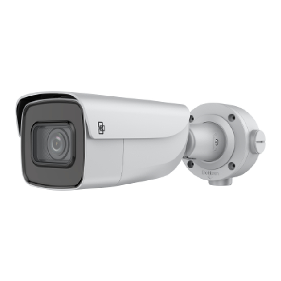
Table 1: Recommended power requirements IP motorized lens bullet camera: 12 VDC or PoE+ (802.3at) IP motorized lens turret camera: 12 VDC or PoE (802.3af) IP motorized lens dome camera: 12 VDC or PoE (802.3af) Camera description Figure 1: IP motorized lens bullet camera Audio: 1 input and 1 12 VDC power input output... - Page 20 Note: To reset the camera to default settings, press and hold the RESET button and power on the camera. After the camera has started up, hold the RESET button for an additional 20 seconds. Figure 2: IP motorized turret camera Camera body 12 VDC power input Trim ring...
- Page 21 Figure 3: IP motorized lens dome camera Bubble assembly Alarm: 1 input and 1 output Lens assembly BNC 960H analog Micro SD card slot output Reset button 12 VDC power input Audio: 1 input and 1 Ethernet RJ45 PoE output port 10.
-
Page 22: Setting Up The Camera
You can configure the IR illumination using a web browser or a client software, such as TruVision Navigator. If the function is enabled, the IR light is On when the camera enters night (black and white) mode. If disabled, the IR light is always Off. -
Page 23: Accessing The Micro Sd Card
The card is not supplied with the camera. Recorded video and log files can be accessed via the web browser or via TruVision Navigator. Mounting the bullet camera Mount the camera on a ceiling or wall. - Page 24 Secure the camera to the back box with the screws. Route the cables through the sealing plugs in the back box. Adjust the viewing angle. 3-axis adjusting (pan/tilt/rotation) allows you to adjust for optimum camera rotation and placement. Follow the steps below to adjust the viewing angle.
-
Page 25: Mounting The Turret Camera
Locking screw Mounting the turret camera To mount the motorized lens turret camera on a ceiling or wall: Use the drill template to mark the mounting holes. Remove the trim ring from the camera. Secure the camera base to the mounting surface with the supplied screws. - Page 26 Adjust the lens position. To adjust the lens position, remove the decorative trim ring by rotating the ring towards the unlocked position (see reference on the trim ring). Loosen the lens adjustment Torx screw that is now visible. Rotate the lens assembly to adjust the pan tilt angle. Tighten the lens adjustment screw to secure the lens at the desired surveillance angle.
-
Page 27: Mounting The Dome Camera
Mounting the dome camera To mount the motorized lens dome camera on a ceiling: Unscrew the bubble from the camera body. Mark four screw holes at desired mounting location. Installation Guide... - Page 28 Secure the mounting adapter plate to ceiling with the four supplied screws. Note: Use expansion screws for a concrete ceiling and self-tapping screws for a wooden ceiling. Attach the camera body to the adapter plate with at least three screws. Installation Guide...
- Page 29 Loosen the tilt adjust screws and adjust the tilt position of the lens assembly within a range of 75 degrees. Retighten the tilt adjust screws. Rotate the dome liner to adjust the pan position within a range of 355 degrees. Rotate the lens assembly (0 to 355°) to obtain the desired surveillance angle.
-
Page 30: Network Access
Network access This guide explains how to configure the camera over the network with a web browser. TruVision IP cameras can be configured and controlled using Microsoft Internet Explorer (IE) and other browsers. The procedures described use Microsoft Internet Explorer web browser. - Page 31 able to interact with the cameras over the web and, if necessary, modify the Active X settings. Configuring IE ActiveX controls You should confirm the ActiveX settings of your web browser. To change the web browser’s security level: In Internet Explorer, click Internet Options on the Tools...
-
Page 32: Activating The Camera
To have complete functionality of the web browser interface with Windows 7, 8, and 10, do the following: • Run the browser interface as an administrator in your workstation • Add the camera’s IP address to your browser’s list of trusted sites To add the camera’s IP address to Internet Explorer’s list of trusted sites:... - Page 33 You can activate a password via a web browser and via TruVision Device Manager (included on the CD to find the IP address of the camera). Activation via the web browser: Power on the camera and connect the camera to the network.
- Page 34 Confirm the password. Click to save the password and enter the live view. Activation via TruVision Device Manager: Run TruVision Device Manager to search for online devices. Check the device status from the device list, and select the inactive device.
-
Page 35: Using The Camera With A Truvision Recorder Or Another System
Input the password and click the Save button to activate your IP address modification. Using the camera with a TruVision recorder or another system Please refer to the NVR/DVR user manuals for instructions on connecting and operating the camera with these systems. -
Page 36: Using The Camera With Truvision Navigator
Using the camera with TruVision Navigator A camera must be connected to an Interlogix NVR in order to be operated by TruVision Navigator. Please refer to the TruVision Navigator user manual for instructions on operating the camera with TruVision Navigator. -
Page 37: Truvision Ip Motorized Lens Turret Dome
TruVision IP motorized lens turret dome Electrical Voltage input 12 VDC, PoE (IEEE 802.3af) Power consumption 2MPX: Max. 11.5 W 4MPX: Max. 12.5 W 8MPX: Max. 12.5 W Miscellaneous Connectors 12 VDC Power Input, Network Port (PoE), Audio In/Out, Alarm In/Out Operating temperature -30 to +60°C (-22 to +140°F) -
Page 38: Pin Definitions
153.3 × 111.6 mm (6.04 × 4.39 in.) Dimensions Weight 0.835 kg (1.8 lbs.) Environmental rating IP67, IK10 Pin definitions There are eight wires on a standard UTP/STP cable and each wire is color-coded. The following shows the pin allocation and color of straight and crossover cable connection: Figure 1: Straight-through cable White/Orange... - Page 39 Figure 2: Cross-over cable White/Orange White/Orange Orange Orange White-Green White-Green Blue Blue White/Blue White/Blue Green Green White/Brown White/Brown Brown Brown Please make sure your connected cables have the same pin assignment and color as above before deploying the cables in your network.
- Page 40 Carrier, except where specifically permitted under US and international copyright law. Trademarks and TruVision names and logos are a product brand of Aritech, a part patents of Carrier. Other trade names used in this document may be trademarks or registered trademarks of the manufacturers or vendors of the respective products.
- Page 41 FCC conditions This device complies with Part 15 of the FCC Rules. Operation is subject to the following two conditions: (1) This device may not cause harmful interference. (2) This Device must accept any interference received, including interference that may cause undesired operation. ACMA compliance Notice! This is a Class A product.
- Page 42 Certification EU directives This product and - if applicable - the supplied accessories too are marked with "CE" and comply therefore with the applicable harmonized European standards listed under the EMC Directive 2014/30/EU, the RoHS Directive 2011/65/EU. 2012/19/EU (WEEE directive): Products marked with this symbol cannot be disposed of as unsorted municipal waste in the European Union.
- Page 43 Installation Guide...
Need help?
Do you have a question about the 6 IP Series and is the answer not in the manual?
Questions and answers