Table of Contents
Advertisement
Quick Links
Advertisement
Table of Contents

Subscribe to Our Youtube Channel
Related Manuals for YOKOGAWA Exner RF20C


Summary of Contents for YOKOGAWA Exner RF20C
- Page 1 Instruction RF20C (EXmatic 460) Manual Control unit IM 12B06K07-E-E 1st Edition...
-
Page 2: Table Of Contents
Table of contents 1 Safety and protection measures 1.1 General safety instructions 1.2 Intended use 1.3 Danger areas and residual dangers 1.4 Resources 1.5 Personnel 1.6 Disposal 1.7 Symbols and icons 2 Product description 2.1 Control unit RF20C (EXmatic 460) 2.2 Process integration 3 Program functions 3.1 Automatic start of cleaning... -
Page 3: Safety And Protection Measures
1. Safety and protection measures 1.4 Resources Only use checked and approved accessories and 1.1 General notes on safety resources. The control unit RF20C (EXmatic 460) is designed in Supply voltage Make sure you have the correct such a way that the product does not present any risk if the operating instructions are adhered to. -
Page 4: Product Description 2.1 Control Unit Rf20C (Exmatic 460)
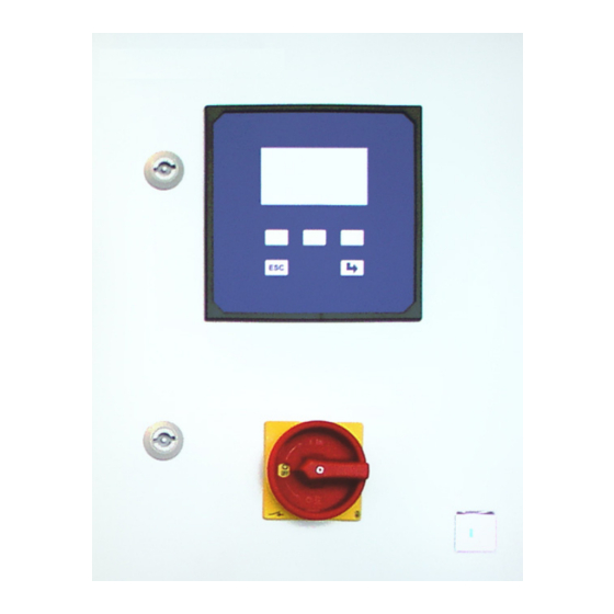
2. Product description 2.1 Control unit RF20C (EXmatic 460) Figure 1: Control unit outside Figure 2: Control unit inside View from outside View from inside 1 Operating panel 6 Terminal board 2 Function keys 7 Indicator/pressure switch 3 Return button 8 Pilot valve 4 ESC button 9 Input multi hose... -
Page 5: Process Integration
2.2 Process integration The control unit RF20C (EXmatic 460) is supplied with 24V DC and with compressed air 4-6 bar. The connection of the retractable fitting and the cleaning and drain valves is realized by pneumatic hoses which are gathered in a multi hose. Process Control System RF20C (EXmatic 460) -
Page 6: Program Functions
3. Program functions 3.1 Automatic start of cleaning 3.2 Seal water In principal, there are 3 different ways of starting For the short time during which the measuring an automatic cleaning cycle. They can also be window moves over the sealing elements, when combined in a useful manner. -
Page 7: Cleaning Program
3.3 Cleaning program As soon as a cleaning program is started (see 3.1), the following functions are run one after the other: Start Loop / Event / Trigger Measure Clean I/1 Clean II Clean II/RT Clean I/2 Pause Measure Trigger OFF Figure 4: Program sequence Cleaning I/1 Cleaning with 1. -
Page 8: Delivery
Air: 4-6 bar T:50ºC CAUTION! made in germany www.e-p-e.com Figure 5: Identification plate DANGER! The identification plate is affixed to the inside of the cabinet door! In case of questions, please contact Yokogawa. WARNING! IM 12B06K07-E-E... -
Page 9: Assembly
Wandmontage CAUTION! Stellen Sie sicher, dass DANGER! 5. Assembly genügend Arbeitsraum für den Betrieb der 5.1 Wall mounting Armaturensteuerung vorhanden ist. Ensure that mögliche Spannungsversorger stromfrei geschaltet sind. • there is enough working space for operating the WARNING! control unit. -
Page 10: Electric Connections
Die Armaturensteuerung muss stromfrei geschaltet und die Druckluft drucklos sein! CAUTION! DANGER! FAHR! 5.2 Electric connections DANGER! Ist die Spannungsversorgung nicht abgeschaltet, besteht Gefahr The control unit must be disconnected from There is the risk for life and limb if the the mains and the compressed air must be voltage supply is not disconnected! für Leib und Leben! -
Page 11: Pneumatic Connections
Filtered air 40µm, water and oil-free 4/6mm 4-6 bar Pin allocation: 5.3 Pneumatic connections Pin allocation: 5.3 Pneumatic connections Contact Description Multi hose Contact Description Multi hose Main Power supply 24VDC 30VA - Control Hose dim./ RF20H/M/C Main Power supply 24VDC 30VA - Control Hose dim./ RF20H/M/C... -
Page 12: Parameterization
CAUTION! 6. Parameterization 6.2 Automatic Mode The parameterized process runs in automatic mode There is the risk of damaging the system or and the display shows the following: DANGER! that process fluid or cleaning solution issues in an uncontrolled manner! Automatic 12:22:17 CAUTION! -
Page 13: Manual Mode
6.3 Manual Mode 6.4 Parameters In Manual Mode, the individual functions can be You can parameterize the times and the functions of chosen manually. the control in the parameters menu. If you have chosen the Manual Mode, you must now enter a pass code: If you have chosen Parameter in the main menu or during the automatic mode, you must now enter the Input Manual Code... - Page 14 If you want to change times, select the desired time The first line shows the currently set starting time. by means of the soft keys and confirm with Enter. You can change this value by pressing the soft The following display is shown: keys.
-
Page 15: System
6.5 System Set Date In the menu point System you can parameterize the In the system mode Set Date, the date can be set. system settings. The following display is shown: Upon selecting System in the main menu, you must enter the pass code: Set Date Input System Code... - Page 16 CAUTION! The outputs and the inputs are assigned as follows: If you change or forget a pass code, you DANGER! block the system access. Write the set No. Output Connection values down and store them at a safe place. Fitting drive 0=Service 1= Measurement 70/71 Drain valve 72/73...
-
Page 17: Maintenance
7. Maintenance 7.1 Important notes on maintenance 7.3 Disposal • Prepare a maintenance plan which is adjusted to your process! Control unit • Maintenance work may only be carried out by Make sure that the control unit is free of hazardous skilled personnel. -
Page 18: Technical Data
8. Technical data 8.1 Standards Noise immune according to the standard EN 61000-6-2 Noise-suppressed according to the standard EN 61000-6-4 8.2 Material Control cabinet Casing glass-reinforced plastic stainless steel option Control unit glass-reinforced plastic casing plexiglass protection cove 8.3 Connected loads Connected loads Voltage supply 24V DC 30 VA... -
Page 19: Spare Parts And Accessories
9. Spare parts and accessories Spare parts Control Spare part Order number RF20C (EXmatic 460) Complete control unit 9-110-00-001 Solenoid valve 5/2-way G ¼“ 24VDC 3,8W (without plug and cable) 9-091-10-001 Solenoid valve 3/2-way G ¼“ 24VDC 3,8W (without plug and cable) 9-091-10-002 Plug with cable for solenoid valve 7-098-20-001... - Page 20 Yokogawa has an extensive sales and YOKOGAWA ELECTRIC CORPORATION YOKOGAWA ELECTRIC ASIA Pte. LTD. 5 Bedok South Road World Headquarters distribution network. 9-32, Nakacho 2-chome, Musashino-shi Singapore 469270 Singapore Tokyo 180-8750 Please refer to the European website Japan www.yokogawa.com/sg www.yokogawa.com (www.yokogawa.com/eu) to contact your...
Need help?
Do you have a question about the Exner RF20C and is the answer not in the manual?
Questions and answers