Table of Contents
Advertisement
Quick Links
Advertisement
Table of Contents

Subscribe to Our Youtube Channel
Related Manuals for HIKVISION DS-3E2300P-H Series


Summary of Contents for HIKVISION DS-3E2300P-H Series
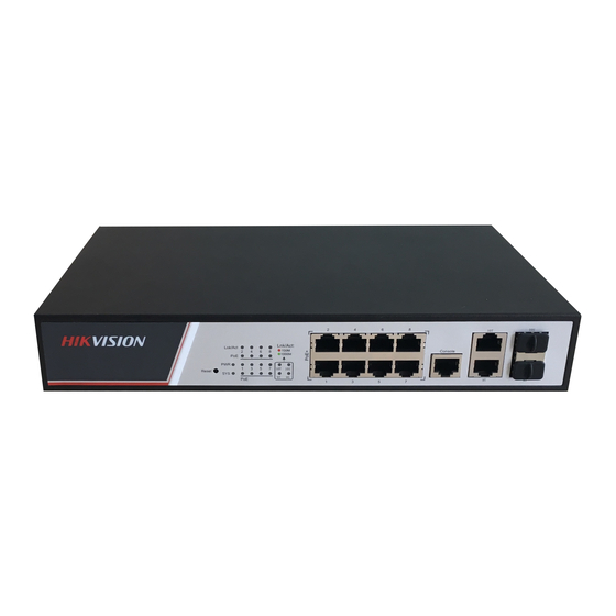
- Page 2 产品简介 HIKVISION DS-3E2300P-H 系列以太网交换机包括如下的产品型号。 名称 具体型号 DS-3E2310P-H DS-3E2300P-H 系列以太网交换机 DS-3E2318P-H DS-3E2326P-H 前面板 下面依次为 DS-3E2310P-H/ DS-3E2318P-H/ DS-3E2326P-H 设备的前 面板示意图。...
- Page 3 (1): 10/100Base-TX 电口 (2): Combo 口 (3): Console 口 (4): 端口状态指示灯 (5): 电源状态指示灯(Power) 后面板 下面依次为 DS-3E2310P-H/ DS-3E2326P-H 设备的后面板示意图。 其中, DS-3E2318P-H 的后面板示意图可参考 DS-3E2326P-H。 (1): 交流电源接口 (2): 接地螺钉 (3): 防盗孔 (4): 直流电源接口...
- Page 4 指示灯说明 指示灯 状态 含义 亮(绿灯) 交换机已通电,且电源模块工作正常 Power 电源指 闪烁 (绿灯) 交换机已通电,且系统正在进行自检 示灯 灭 交换机未通电或电源模块发生故障 端口工作在 10/100Mbps 速率下 亮(绿灯) Link/Act 状态指 端口与对端设备有连接,且连接正常 示灯 端口工作在 10/100Mbps 速率下 (10/100BASE 闪烁 (绿灯) 端口在收发数据 -TX 电口) 灭 端口与对端设备无连接或端口连接失败 端口工作在 1000Mbps 速率下 亮(绿灯) 端口与对端设备有连接,且连接正常 端口工作在 1000Mbps 速率下 闪烁...
- Page 5 指示灯 状态 含义 端口工作在 1000Mbps 速率下 亮(绿灯) 端口与对端设备有连接,且连接正常 端口工作在 1000Mbps 速率下 闪烁 (绿灯) Link/Act 状态指 端口在收发数据 示灯 端口工作在 100Mbps 速率下 (100/1000Ba 亮(黄灯) 端口与对端设备有连接,且连接正常 se-X SFP 光口) 端口工作在 100Mbps 速率下 闪烁 (黄灯) 端口在收发数据 灭 端口与对端设备无连接或端口连接失败 亮(橙灯) 端口为对端设备供电正常 PoE 端口状态 闪烁 (橙灯) 端口为对端设备供电异常 指示灯...
- Page 6 请确保交换机在一个正确、稳定的电压下工作; 在使用交换机前,请务必通过交换机后面板的接地端子可靠接地; 在清洁交换机前,应先将交换机电源插头拔出。请不要用湿润的布料 擦拭交换机,也不要使用液体清洗交换机; 在交换机工作时请不要打开机壳。即使在不带电的情况下,也不要随 意打开交换机机壳,以免操作不当损坏设备。 此为 A 级产品,在生活环境中,该产品可能会造成无线电干扰。在这种情 况下,可能需要用户对其干扰采取切实可行的措施。 安装到 19 英寸标准机柜 仅 DS-3E2318P-H 和 DS-3E2326P-H 支持此安装方式。 安装过程如下(以 DS-3E2326P-H 为例进行介绍): 步骤1 检查机柜的接地与稳定性。 步骤2 用螺钉将安装挂耳固定在交换机前面板两侧。 步骤3 将交换机放置在机柜的一个托架上,沿机柜导槽移动交换机至 合适位置。...
- Page 7 步骤4 用螺钉将安装挂耳固定在机柜两端的固定导槽上,确保交换机 稳定地安装在机柜槽位的托架上。 设备的挂耳并不用来承重,它只起固定作用。安装设备于机柜时,设备机 箱的下边要有托架(固定在机柜上)来支撑设备。 安装交换机到工作台 您也可以直接将交换机放置在干净、稳固、接地良好的工作台上。安装过 程如下: 步骤1 小心地将交换机倒置。用软布清洁交换机机箱底板上的凹槽, 确保没有油污或灰尘吸附。 步骤2 撕掉随机附带的脚垫表面的粘贴纸,将脚垫粘贴到交换机机箱 底板上的凹槽内。 步骤3 小心将交换机正置,放在工作台上。...
- Page 8 连接线缆 连接配置电缆 通过终端配置交换机时,配置电缆的连接步骤如下: 步骤1 将配置电缆的 DB-9 孔式插头接到要对交换机进行配置的 PC 的 串口上。 步骤2 将配置电缆的 RJ-45 一端连到交换机的配置口(Console)上。 连接接地线 接地线的正确连接是设备防雷、防电磁干扰的重要保障。设备连接接地线 的步骤如下: 步骤1 用十字螺丝刀将设备接地点上的接地螺钉取下并妥善放置,将 接地螺钉穿过接地线 OT 端子的圆孔, 用十字螺丝刀顺时针方向 旋转接地螺钉将接地线 OT 端子紧固在设备的接地点上。 步骤2 用尖嘴钳将接地线的另一端绕成一个圆圈。...
- Page 9 步骤3 将接地线的另一端连接至接地排上,用扳手顺时针方向旋转六 角螺母将接地线的另一端紧固在接地柱上。 连接电源线 此处以 DS-3E2310P-H 和 DS-3E2326P-H 为例依次进行介绍。 DS-3E2318P-H 和 DS-3E2326P-H 连 接 电 源 线 的 方 法 相 似 , 参 考 DS-3E2326P-H 即可。 连接交流电源线 连接电源线之前请确保设备已可靠接地。连接电源线的步骤如下: 步骤1 将随机附带的电源线的一端准确到位地插入到设备的交流电源 插孔上。 步骤2 安装电源线卡钩。 步骤3 用电源线卡钩固定好电源线,防止电源线脱落。 步骤4 将电源线的另一端连接到外部的交流电源插座上。...
- Page 11 RPS直流电源接口电源线连接 DS-3E2318P-H 和 DS-3E2326P-H 除了支持交流电源供电外,还支持 RPS 直流电源供电,交、直流可以同时输入,互为备份,也可以只输入 交流或者直流。仅 RPS 直流电源供电时,输入电压为-47~-57V;若交、 直流同时供电时,则直流的输入电压范围要为-54~-57V,若超出这个电 压范围,则只能通过交流电源供电。 其电源线连接过程如下: 步骤1 确认接地线缆已连接,并保证交换机良好接地。 步骤2 拆掉 RPS 直流电源接口上的盖板,插入 RPS 直流电源线并保 证直流电源线插头上下方向正确(如果上下倒置,安装过程将 受到电源模块直流输入插口和电源线插头特殊设计的结构限制, 不能顺利进行) 。 步骤3 用一字螺丝刀顺时针方向拧紧 RPS 电源线交换机侧插头两侧自 带的螺钉,使电源线插头固定在 RPS 直流输入插口上。 步骤4 将直流电源线另一端接到外置 RPS 电源的输出功率不小于 810W 的输出接口上。 步骤5 检查交换机前面板 RPS 电源指示灯是否变亮,灯亮则表示电源 线连接正确。...
- Page 12 安装SFP光模块并连接光纤 安装 SFP 光模块时,请勿触碰 SFP 光模块的金手指部分; 建议用户在连接光纤前,不要将 SFP 光模块的防尘塞拔出; 建议用户不要将已插有光纤的 SFP 光模块直接插入插槽,请拔出光纤 后再进行安装。 安装 SFP 光模块并连接光纤的步骤如下: 步骤1 佩戴防静电手腕,确保防静电手腕与皮肤良好接触并可靠接地。 步骤2 将 SFP 光模块的拉手向上垂直翻起,用手捏住光模块两侧,沿 水平方向将光模块轻推入插槽,直至光模块与插槽紧密接触。 步骤3 去掉光纤的 LC 连接器的防尘帽以及 SFP 光模块的防尘塞。 步骤4 将光纤的 LC 连接器连接到 SFP 光模块。...
- Page 13 登录设备 交换机的管理地址默认是通过 DHCP 获取的,初次登录交换机只能通过 Console 口进行本地登录。可通过 display ip interface 命令查看实际获 取到的 IP 地址。通过 Console 口进行本地登录是登录交换机的最基本的 方式, 也是配置通过其他方式登录交换机的基础。 有关这部分内容的介绍, 请参见公司网站上对应产品的配置命令手册。 技术规格 属性 DS-3E2310P-H DS-3E2318P-H DS-3E2326P-H 外形尺寸(W 330 mm×230 440 mm×260 mm×44 mm ×D×H) mm×44 mm 重量 ≤ 2.5kg ≤ 4kg 8 个 16 个...
- Page 14 连接器类型:RJ-45 电口属性 支持半双工、全双工、自协商工作模式 支持 MDI/MDI-X 整机漏电流 满足 GB4943.1 标准 AC:100V~240V AC,50/60Hz 输入电压 DC:-54~-57V;19.5A(仅适用于 DS-3E2318P-H 和 DS-3E2326P-H) 连接器类型:LC 光口属性 支持 1000Mbit/s 传输速率 全双工 支持 100Mbit/s 传输速率 全双工 工作温度 0°C~40°C 工作湿度 5%~95%,非凝露 防火要求 满足 GB4943.1 标准 版权所有©杭州海康威视数字技术股份有限公司 2018 地址:杭州海康威视数字技术股份有限公司 网址: http:// www.hikvision.com...
- Page 15 Quick Setup Guide...
- Page 16 Hikvision DS-3E2300P-H Quick Setup Guide Hangzhou Hikvision Digital Technology Co., Ltd. http://overseas.hikvision.com/en/ Document version: 6PW101-20180419...
- Page 17 Any and all information, including, among others, wordings, pictures, graphs are the properties of Hangzhou Hikvision Digital Technology Co., Ltd. or its subsidiaries (hereinafter referred to be “Hikvision”). This user manual (hereinafter referred to be “the Manual”) cannot be reproduced, changed, translated, or distributed, partially or wholly, by any means, without the prior written permission of Hikvision.
- Page 18 SURVEILLANCE LAWS VARY BY JURISDICTION. PLEASE CHECK ALL RELEVANT LAWS IN YOUR JURISDICTION BEFORE USING THIS PRODUCT IN ORDER TO ENSURE THAT YOUR USE CONFORMS THE APPLICABLE LAW. HIKVISION SHALL NOT BE LIABLE IN THE EVENT THAT THIS PRODUCT IS USED WITH ILLEGITIMATE PURPOSES.
-
Page 19: Preparing For Installation
Preparing for installation The HIKVISION DS-3E2300P-H Ethernet Switch Series includes the following models: • DS-3E2310P-H • DS-3E2318P-H • DS-3E2326P-H Safety recommendations To avoid any equipment damage or bodily injury, read the following safety recommendations before installation. The recommendations do not cover every possible hazardous condition. -
Page 20: Installing The Switch
NOTE: The switch is a class-A device and might cause electromagnetic interference (EMI). Take actions to prevent EMI when necessary. Installing the switch Rack mounting Only the DS-3E2318P-H and DS-3E2326P-H support rack mounting. This section uses a DS-3E2326P-H switch as an example. To install the switch in a 19-inch rack: Verify that the rack is reliably grounded and is stable. -
Page 21: Horizontal Surface Mounting
Figure 2 Attaching mounting brackets to the rack posts NOTE: Mounting brackets are used only for securing the switch to the rack. A rack shelf on the rack is required to bear the switch weight. Horizontal surface mounting Verify that the horizontal surface is sturdy and reliably grounded. Place the switch bottom up, and clean the round holes in the chassis bottom with a dry cloth. -
Page 22: Connecting The Console Cable
Connecting cables Connecting the console cable Perform this task to connect the switch to a PC to configure the switch through the PC. To connect the console cable: Connect the DB-9 connector of the console cable to the serial port of the PC. - Page 23 To connect the grounding cable: Remove the grounding screw from the rear panel of the switch chassis. Attach the grounding screw to the ring terminal of the grounding cable. Use a Phillips screwdriver to fasten the grounding screw into the grounding screw hole.
- Page 24 Pull the bail latch down (DS-3E2310P-H) or left (DS-3E2326P-H) to secure the power cord to the power receptacle. Connect the other end of the AC power cord to the AC power outlet. Figure 5 Connecting the AC power cord for the DS-3E2310P-H Figure 6 Connecting the AC power cord for the DS-3E2326P-H...
- Page 25 Connecting the RPS DC power cord for the DS-3E2318P-H and DS-3E2326P-H The RPS DC power cord is user supplied and must be shorter than 3 m (9.84 ft). To connect the RPS DC power cord: Wear an ESD wrist strap and make sure it makes good skin contact and is reliably grounded.
-
Page 26: Installing The Sfp Transceiver Module And Optical Fibers
Installing the SFP transceiver module and optical fibers CAUTION: • Hold the SFP transceiver module by its two sides when you install or remove the module. Do not touch the golden plating of the module. • Do not remove the dust plug from the transceiver module before installing the optical fibers. -
Page 27: Accessing The Switch For The First Time
Accessing the switch for the first time The first time you access the switch, you can only log in to the CLI through the console port. For more information, visit the website http://www.hikvision.com to see the configuration guide and command reference for the switch. - Page 28 Figure 11 Rear panel (1) AC power receptacle (2) Grounding screw (3) Security slot DS-3E2318P-H Figure 12 Front panel (1) 10/100BASE-TX copper ports (2) Combo interface (3) Console port (4) Port status LEDs (5) Power status LED Figure 13 Rear panel (1) AC power receptacle (2) Grounding screw (3) DC power receptacle...
-
Page 29: Technical Specifications
DS-3E2326P-H Figure 14 Front panel (1) 10/100BASE-TX copper ports (2) Combo interface (3) Console port (4) Port status LEDs (5) Power status LED Figure 15 Rear panel (1) AC power receptacle (2) Grounding screw (3) DC power receptacle Technical specifications Table 1 Technical specifications DS-3E2310P- DS-3E2318P-... - Page 30 DS-3E2310P- DS-3E2318P- Item DS-3E2326P-H ≤ 2.5 kg (5.51 Weight ≤ 4 kg (8.82 lb) ≤ 4 kg (8.82 lb) 8 × 16 × 24 × 10/100BASE- 10/100BASE-T 10/100BASE-T TX copper X copper port X copper port Ethernet port port 2 × combo 2 ×...
-
Page 31: Appendix B Leds
DS-3E2310P- DS-3E2318P- Item DS-3E2326P-H Overall leakage GB4943.1 current AC: 100 VAC to 240 VAC @ 50 Hz or 60 Hz Input voltage DC: –54 to –57 VDC @ 19.5 A (for DS-3E2318P-H and DS-3E2326P-H only) Operating 0°C to 40°C (32°F to 104°F) temperature Relative 5% to 95%, noncondensing... - Page 32 Status Description Steady green A 10/100-Mbps link is present. Link/ACT LEDs Flashing The port is receiving or sending (10/100BASE- green data at 10/100 Mbps. TX copper port) No link is present. Steady green A 1000-Mbps link is present. Flashing The port is receiving or sending green data at 1000 Mbps.
- Page 33 Status Description RPS LED (for Steady green RPS DC power input is normal. DS-3E2318P- No RPS DC power is provided or H and RPS DC power input is DS-3E2326P- abnormal. H only)
- Page 34 网 址:http:// www.hikvision.com 地 址:杭州市滨江区阡陌路 555 号 邮 编:310051...
Need help?
Do you have a question about the DS-3E2300P-H Series and is the answer not in the manual?
Questions and answers